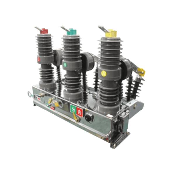
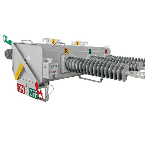
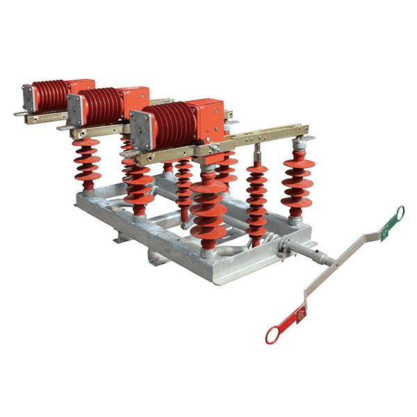
Description
Automatic Circuit Recloser (ACR) Features
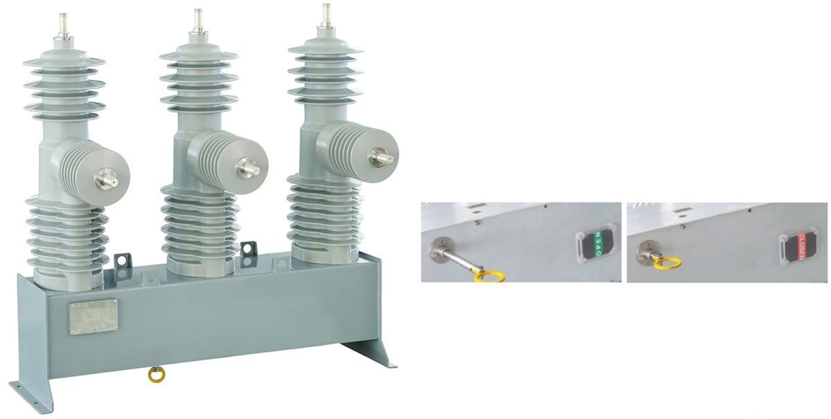
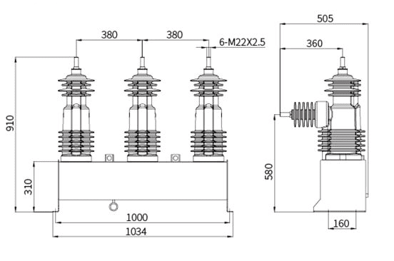
27kV External Dimension
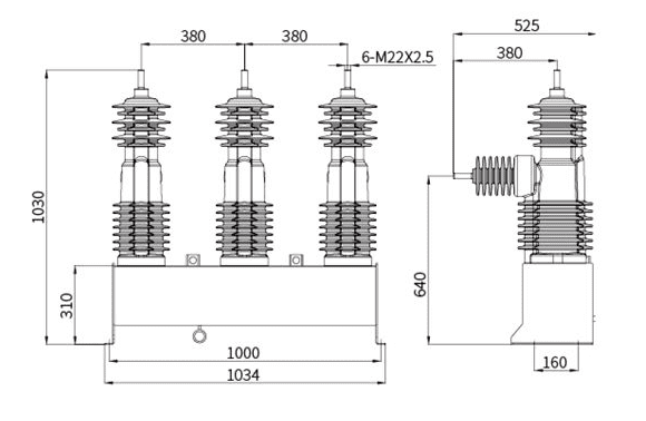
38kV External Dimension
Technical Parameters
| 15.5kV 50/60Hz |
Rated continuous current | Rated duration of short-circuit | Rated short-circuit making curent | Rated short-circuit breaking current | Rated lightning impulse withstand voltage | Rated short-duration P.F. withstand voltage | Impedance μΩ between connections | Creepage distance phase-to-earth | Clearance phase-to-phase | Minimum clearance, phase-to-earth | Weight | Line charging current | Cable charging current | Max.interrupting time/max. closing time |
| Ir/A | Tk/s | Isc/kA | Ima/kA | Up/kv | Ud/kV | μΩ | mm | mm | mm | kg | A | A | ms | |
| YVZ15-630/12/N | 630 | 3 | 12.5 | 31.5 | 110 | 50 | 60 | 960 | 320 | 270 | 130 | 2 | 10 | 40/60 |
| YVZ15-800/12/N | 800 | 3 | 12.5 | 31.5 | 110 | 50 | 60 | 960 | 320 | 270 | 130 | 2 | 10 | 40/60 |
| YVZ15-630/16/N | 630 | 3 | 16 | 40 | 110 | 50 | 60 | 960 | 320 | 270 | 130 | 2 | 10 | 40/60 |
| YVZ15-630/16/N | 800 | 3 | 16 | 40 | 110 | 50 | 60 | 960 | 320 | 270 | 130 | 2 | 10 | 40/60 |
| 27kV 50/60Hz |
Ir/A | Tk/s | Isc/kA | Ima/kA | Up/kv | Ud/kV | μΩ | mm | mm | mm | kg | A | A | ms |
| YVZ27-630/12/N | 630 | 3 | 12.5 | 31.5 | 130 | 60 | 60 | 1080 | 320 | 270 | 130 | 5 | 25 | 40/60 |
| YVZ27-800/12/N | 800 | 3 | 12.5 | 31.5 | 130 | 60 | 60 | 1080 | 320 | 270 | 130 | 5 | 25 | 40/60 |
| YVZ27-630/16/N | 630 | 3 | 16 | 40 | 130 | 60 | 60 | 1080 | 320 | 270 | 130 | 5 | 25 | 40/60 |
| YVZ27-800/16/N | 800 | 3 | 16 | 40 | 130 | 60 | 60 | 1080 | 320 | 270 | 130 | 5 | 25 | 40/60 |
| YVZ27-630/16/H | 630 | 3 | 16 | 40 | 170 | 70 | 60 | 1290 | 320 | 350 | 148 | 5 | 25 | 40/60 |
| YVZ27-800/16/H | 800 | 3 | 16 | 40 | 170 | 70 | 60 | 1290 | 320 | 350 | 148 | 5 | 25 | 40/60 |
| 38kV 50/60Hz |
Ir/A | Tk/s | Isc/kA | Ima/kA | Up/kv | Ud/kV | μΩ | mm | mm | mm | kg | A | A | ms |
| YVZ38-630/12/N | 630 | 3 | 12.5 | 31.5 | 170 | 70 | 60 | 1290 | 320 | 350 | 148 | 5 | 40 | 40/60 |
| YVZ38-800/12/N | 800 | 3 | 12.5 | 31.5 | 170 | 70 | 60 | 1290 | 320 | 350 | 148 | 5 | 40 | 40/60 |
| YVZ38-630/16/N | 630 | 3 | 16 | 40 | 170 | 70 | 60 | 1290 | 320 | 350 | 148 | 5 | 40 | 40/60 |
| YVZ38-800/16/N | 800 | 3 | 16 | 40 | 170 | 70 | 60 | 1290 | 320 | 350 | 148 | 5 | 40 | 40/60 |
Dimensions for Mounting
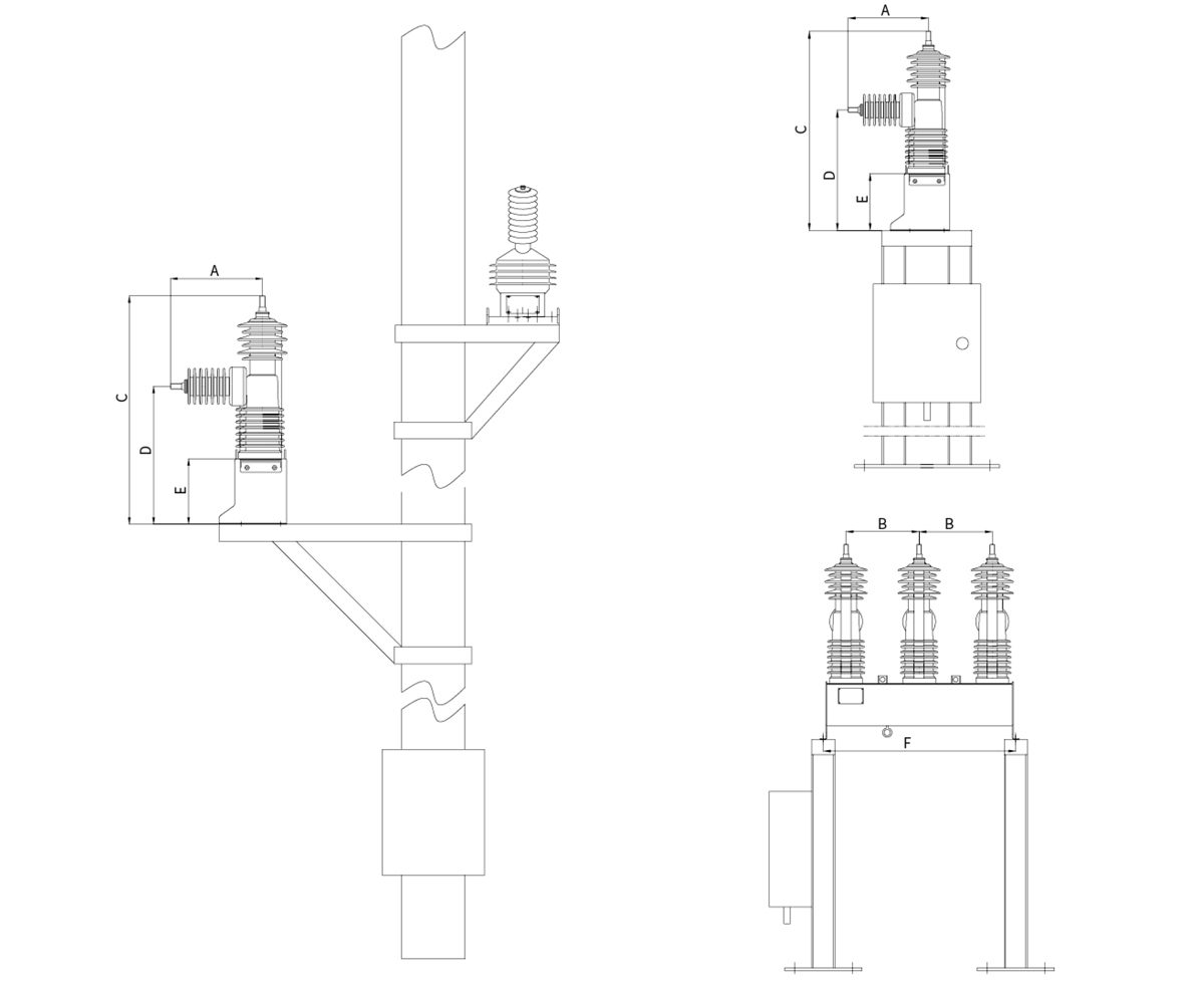
| A | B | C | D | E | F | ||
| 15.5kV | mm | 505 | 380 | 910 | 580 | 310 | 1000 |
| 27kV | mm | 505 | 380 | 910 | 580 | 310 | 1000 |
| 38kV | mm | 525 | 380 | 1030 | 640 | 310 | 1000 |
Description of Controller
Controller
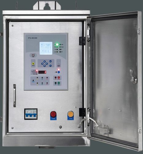
The Microprocessor based controller provides protection, control, monitoring, instrumentation and metering with integrated input and output logic, data logging & fault report.
Communication functionality of the controller is achieved via electrical RS485 port for remote connection. Additional rear ports including RS232 are available for selection.
The Feeder Terminal Unit(FTU) is the core of controller. To prevent any damage to FTU from emergency, the control cubicle contains auxiliary power supply of batteries for uninterruptible power supply, electronic boards and circuit breakers.
A series of protection functions can be set via screen display.
Protection
● Protective Functions
● Phase time overcurrent protection (51P)
● Phase instantaneous overcurrent protection (50P-1)
● Two definite time overcurrent settings (50P-2, 50P-3)
● Ground overcurrent protection (51N)
● Ground instantaneous overcurrent protection (50N-1)
●Two definite time ground overcurrent settings (50N-2, 50N-3)
● Negative sequence overcurrent protection (46)
● Phase and ground directional overcurrent protection ( 67P, 67N;)
● Over-frequency (810, 81V)
● Undervoltage and overvoltage control and alarm (27, 59;)
● Up to four reclose cycles (define a recloser cycle 79-1 79-5; ) close fourtimes / trip five
● Adaptive reclosing shots: each reclose sequence allows independent programming of protective functions Sensitive Earth Fault protection
Current input
| Current input | |
| Measuring range: | 0-99A |
| Power consumption: | Rated 5A, each phase is not greater than 0.5VA |
| Rated 1A, each phase is not greater than 0.2VA | |
| Rated at 0.2A, not more than 0.1VA per phase | |
| Overload capacity: | 3 times the rated current, continuous work |
| 20 times the rated current for 4s | |
| 50 times the rated current for 1s | |
Voltage input
Measuring range: 0~ 3V
Power consumption: each phase is not greater than 0.3VA
Overload capacity: 1.4 times the rated value, continuous work
Output
Continuous bearing: 5A
Breaking capacity: DC, inductive load,L / R = 40ms, 220V /0.5A .
Debounce time: 1 ~ 99ms, step 1ms
RS485/RS232
Rate: 1200-38400bps
Default rate: 9600bps
Protocol: Modbus RTU, 1EC60870-5- 101,DNP3.0
Ethernet port (ONLY BC500)
Mode: 10/ 100M (adaptive)
Interface: RJ45
Protocol: Modbus TCP 1 IP,DNP3.0 1EC60870-5 104
Cubicle
The cubicle is integrated with a variety of electronic components, including protection relay and
UPS system for device. Extra components and functions are optional.
