| General specifications |
Product Name |
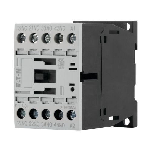
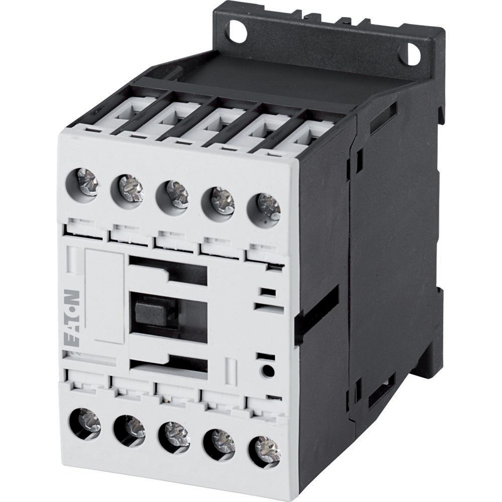
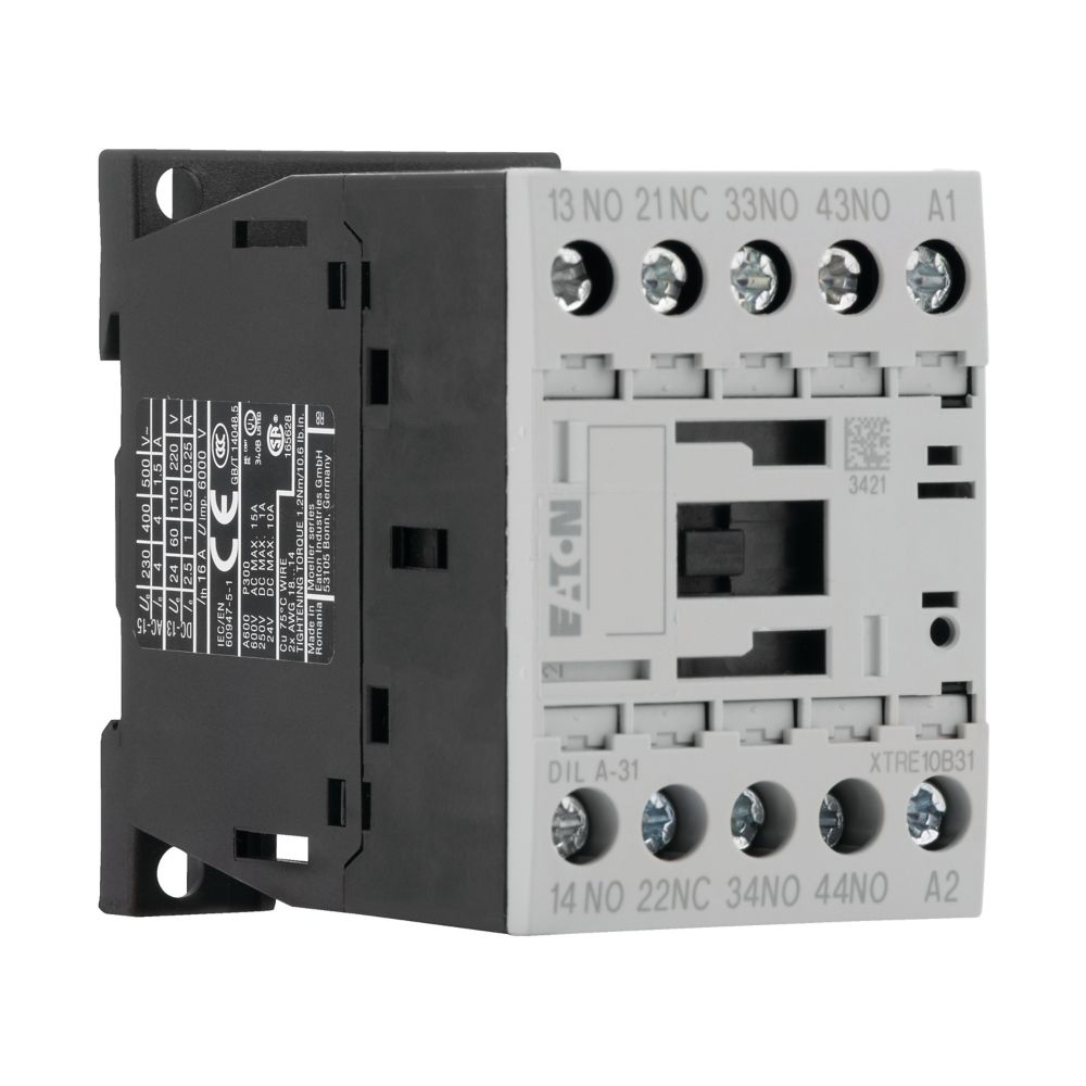
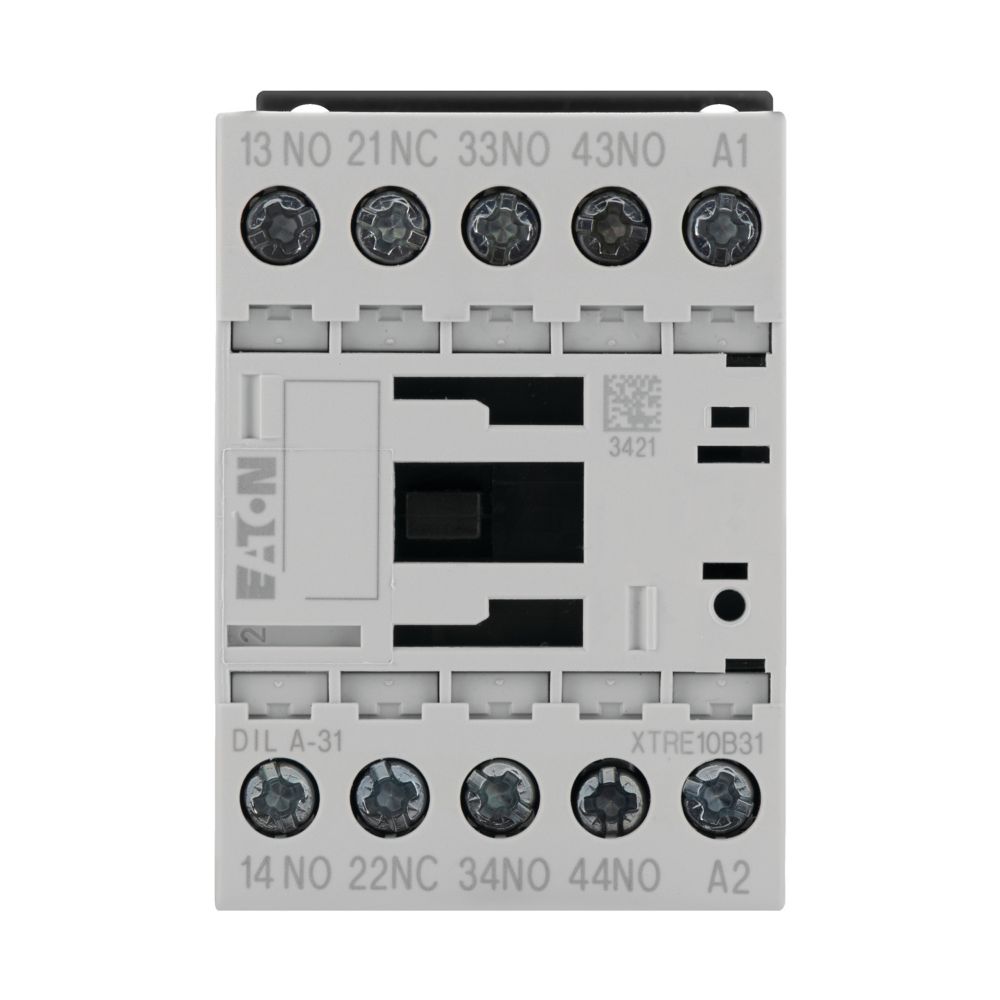
Eaton Moeller® series DILA Control Relay |
|
Catalog Number |
276364 |
|
Model Code |
DILA-31(230V50HZ,240V60HZ) |
|
EAN |
4015082763640 |
|
Product Length/Depth |
75 mm |
|
Product Height |
68 mm |
|
Product Width |
45 mm |
|
Product Weight |
0.24 kg |
|
Certifications |
UL UL File No.: E29184 CSA File No.: 012528 EN 60947-5-1 CE CSA CSA Class No.: 3211-03 CSA-C22.2 No. 14-05 VDE 0660 IEC/EN 60947-4-1 IEC/EN 60947 UL 508 UL Category Control No.: NKCR |
| Product specifications |
Rated operational current for specified heat dissipation (In) |
15.5 A |
|
Terminal capacity (flexible with ferrule) |
1 x (0.75 – 2.5) mm², Screw terminals 2 x (0.75 – 2.5) mm², Screw terminals |
|
10.11 Short-circuit rating |
Is the panel builder’s responsibility. The specifications for the switchgear must be observed. |
|
Rated control supply voltage (Us) at AC, 50 Hz – min |
230 V |
|
Conventional thermal current ith at 60°C (3-pole, open) |
16 A |
|
10.4 Clearances and creepage distances |
Meets the product standard’s requirements. |
|
Mounting method |
DIN-rail/screw |
|
Operating voltage at DC – max |
220 VDC |
|
10.2.3.1 Verification of thermal stability of enclosures |
|
|
Ambient storage temperature – min |
40 °C |
|
Fitted with: |
Positive operation contacts |
|
Rated control supply voltage (Us) at AC, 50 Hz – max |
|
|
Operating voltage at DC – min |
24 VDC |
|
Ambient operating temperature – max |
60 °C |
|
Features |
Positive operating contacts to EN 60947-5-1 appendix L, including auxiliary contact module |
|
Ambient operating temperature – min |
-25 °C |
|
10.6 Incorporation of switching devices and components |
Does not apply, since the entire switchgear needs to be evaluated. |
|
10.2.6 Mechanical impact |
|
|
10.3 Degree of protection of assemblies |
|
|
Application |
Contactor relays |
|
Rated operational current (Ie) at AC-15, 380 V, 400 V, 415 V |
4 A |
|
Operating frequency |
9000 Operations/h |
|
Voltage type |
AC |
|
Product category |
DILA relays |
|
Power consumption, pick-up, 50 Hz |
24 VA, AC, Single-frequency coil 50 Hz and Dual-frequency coil 50/60 Hz |
|
Heat dissipation capacity Pdiss |
0 W |
|
Connection type (auxiliary circuit) |
Screw connection |
|
Short-circuit protection rating without welding |
10 A gG/gL, 500 V, Max. Fuse, Contacts |
|
Switching time (AC operated, make contacts, opening delay) – min |
9 ms |
|
Operating voltage at AC, 60 Hz – max |
500 V |
|
Terminal capacity (solid/stranded AWG) |
18 – 14, Screw terminals |
|
10.9.2 Power-frequency electric strength |
Is the panel builder’s responsibility. |
|
Degree of protection |
IP20 |
|
Overvoltage category |
III |
|
Switching time (AC operated, make contacts, opening delay) – max |
18 ms |
|
Ambient storage temperature – max |
80 °C |
|
Voltage type of operating voltage |
AC/DC |
|
Pollution degree |
3 |
|
Power consumption, pick-up, 60 Hz |
|
|
Switching time (AC operated, make contacts, closing delay) – max |
21 ms |
|
Rated impulse withstand voltage (Uimp) |
6000 V AC |
|
Operating voltage at AC, 60 Hz – min |
17 V |
|
10.2.2 Corrosion resistance |
|
|
10.2.4 Resistance to ultra-violet (UV) radiation |
|
|
10.2.7 Inscriptions |
|
|
Number of contacts (normally open contacts) |
|
|
Switching time (AC operated, make contacts, closing delay) – min |
15 ms |
|
Number of auxiliary contacts (normally open contacts) |
|
|
Shock resistance |
5 g, N/C auxiliary contact, Basic unit with auxiliary contact module, Mechanical, according to IEC/EN 60068-2-27, Half-sinusoidal shock 10 ms 7 g, N/O auxiliary contact, Basic unit with auxiliary contact module, Mechanical, according to IEC/EN 60068-2-27, Half-sinusoidal shock 10 ms |
|
Power consumption, sealing, 60 Hz |
1.4 W, AC, Single-frequency coil 50 Hz and Dual-frequency coil 50/60 Hz |
|
Ambient operating temperature (enclosed) – min |
25 °C |
|
Operating voltage at AC, 50 Hz – max |
|
|
10.12 Electromagnetic compatibility |
|
|
10.2.5 Lifting |
|
|
Number of auxiliary contacts (normally closed contacts, delayed switching) |
0 |
|
Stripping length (main cable) |
10 mm |
|
Ambient operating temperature (enclosed) – max |
|
|
Rated control supply voltage (Us) at DC – min |
0 V |
|
10.8 Connections for external conductors |
|
|
Screw size |
M3.5, Terminal screw |
|
Number of auxiliary contacts (normally open contacts, leading) |
|
|
Protection |
Finger and back-of-hand proof, Protection against direct contact when actuated from front (EN 50274) |
|
Power consumption, sealing, 50 Hz |
1.4 W, AC, Single-frequency coil 50 Hz and Dual-frequency coil 50/60 Hz 3.4 VA, AC, Single-frequency coil 50 Hz and Dual-frequency coil 50/60 Hz |
|
Climatic proofing |
Damp heat, constant, to IEC 60068-2-78 Damp heat, cyclic, to IEC 60068-2-30 |
|
Code number |
31E |
|
Connection to SmartWire-DT |
No |
|
Static heat dissipation, non-current-dependent Pvs |
1.4 W |
|
Rated operational current (Ie) at AC-15, 500 V |
1.5 A |
|
Rated control supply voltage (Us) at DC – max |
|
|
10.9.3 Impulse withstand voltage |
|
|
10.5 Protection against electric shock |
|
|
Safe isolation |
400 V AC, Between auxiliary contacts, According to EN 61140 400 V AC, Between coil and auxiliary contacts, According to EN 61140 |
|
Operating voltage at AC, 50 Hz – min |
|
|
Rated operational current (Ie) at AC-15, 220 V, 230 V, 240 V |
|
|
10.13 Mechanical function |
The device meets the requirements, provided the information in the instruction leaflet (IL) is observed. |
|
10.9.4 Testing of enclosures made of insulating material |
|
|
Number of contacts (normally closed contacts) |
1 |
|
Heat dissipation per pole, current-dependent Pvid |
0.5 W |
|
Switching capacity (auxiliary contacts, general use) |
1 A, 250 V DC, (UL/CSA) 15 A, 600 V AC, (UL/CSA) |
|
Equipment heat dissipation, current-dependent Pvid |
|
|
Rated switch current |
|
|
Rated operational current (Ie) |
1 A at 220 V, DC L/R ≤ 15 ms (with 1 contact in series) 3 A at 110 V, DC L/R ≤ 15 ms (with 1 contact in series) 1 A at 220 V, DC L/R ≤ 50 ms (with 3 contacts in series) 10 A at 24 V, DC L/R ≤ 15 ms (with 1 contact in series) 4 A at 60 V, DC L/R ≤ 50 ms (with 3 contacts in series) 6 A at 110 V, DC L/R ≤ 15 ms (with 3 contacts in series) 5 A at 220 V, DC L/R ≤ 15 ms (with 3 contacts in series) 2 A at 110 V, DC L/R ≤ 50 ms (with 3 contacts in series) 6 A at 60 V, DC L/R ≤ 15 ms (with 1 contact in series) 10 A at 60 V, DC L/R ≤ 15 ms (with 2 contacts in series) 4 A at 24 V, DC L/R ≤ 50 ms (with 3 contacts in series) 16 A |
|
Pick-up voltage |
0.8 – 1.1 V AC x Uc (voltage tolerance – single-voltage coil 50 Hz and dual-voltage coil 50 Hz, 60 Hz) |
|
Terminal capacity (solid) |
1 x (0.75 – 4) mm², Screw terminals 2 x (0.75 – 2.5) mm², Screw terminals |
|
Number of auxiliary contacts (normally closed contacts) |
|
|
10.2.3.2 Verification of resistance of insulating materials to normal heat |
|
|
10.2.3.3 Resist. of insul. mat. to abnormal heat/fire by internal elect. effects |
|
|
Lifespan, mechanical |
20,000,000 Operations (AC operated) |
|
Control circuit reliability |
< 2 λ, < 1 failure at 100,000,000 Operations (at Uₑ = 24 V DC, Umin = 17 V, Imin = 5.4 mA) |
|
Number of auxiliary contacts (change-over contacts) |
|
|
Rated operational voltage (Ue) at AC – max |
690 V |
|
Rated control supply voltage (Us) at AC, 60 Hz – min |
240 V |
|
10.7 Internal electrical circuits and connections |
|
|
10.10 Temperature rise |
The panel builder is responsible for the temperature rise calculation. Eaton will provide heat dissipation data for the devices. |
|
Screwdriver size |
2, Terminal screw, Pozidriv screwdriver 0.8 x 5.5/1 x 6 mm, Terminal screw, Standard screwdriver |
|
Duty factor |
100 % |
|
Rated control supply voltage (Us) at AC, 60 Hz – max |
|
|
Switching capacity (auxiliary contacts, pilot duty) |
P300, DC operated (UL/CSA) A600, AC operated (UL/CSA) |
|
Rated insulation voltage (Ui) |
|
| Catalogs |
Product Range Catalog Switching and protecting motors |
|
|
Switching and protecting motors – catalog |
|
| Characteristic curve |
210U159 |
|
|
eaton-contactors-component-dila-relay-characteristic-curve.eps |
|
|
eaton-contactors-dila-relay-characteristic-curve.eps |
|
|
210U161 |
|
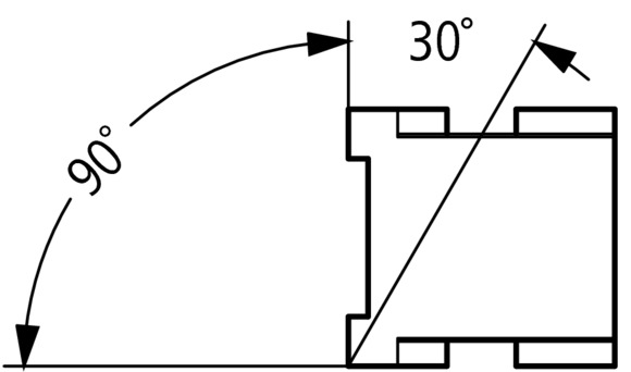
| Drawings |
eaton-contactors-frame-dilm-dimensions.eps |
|
|
210N018 |
|
|
210T013 |
|
|
eaton-contactors-mounting-dilm-dimensions.eps |
|
|
210N017 |
|
|
eaton-contactors-mounting-dilm-dimensions-002.eps |
|
|
eaton-contactors-module-dilm-dimensions.eps |
|
|
2110DIM-1 |
|
|
210I044 |
|
|
eaton-contactors-dilm-3d-drawing-007.eps |
|
| eCAD model |
ETN.DILA-31(230V50HZ,240V60HZ) |
|
| Installation instructions |
IL03407013Z |
|
| mCAD model |
DA-CD-dil_m7_15 |
|
|
DA-CS-dil_m7_15 |
|
| PEP Eco-passport |
EATO-00023-V01.01-EN |
|
| Specifications and datasheets |
Eaton Specification Sheet – 276364 |
|
| System overview |
210O133 |
|
|
eaton-contactors-dila-system-overview.eps |
|
| Wiring diagrams |
210S012 |
|
|
eaton-contactors-contact-diler-relay-wiring-diagram-002.eps |
|
|
2100SWI-110 |
|
| Date |
Thu Jul 20 2023 |
|

