| General specifications |
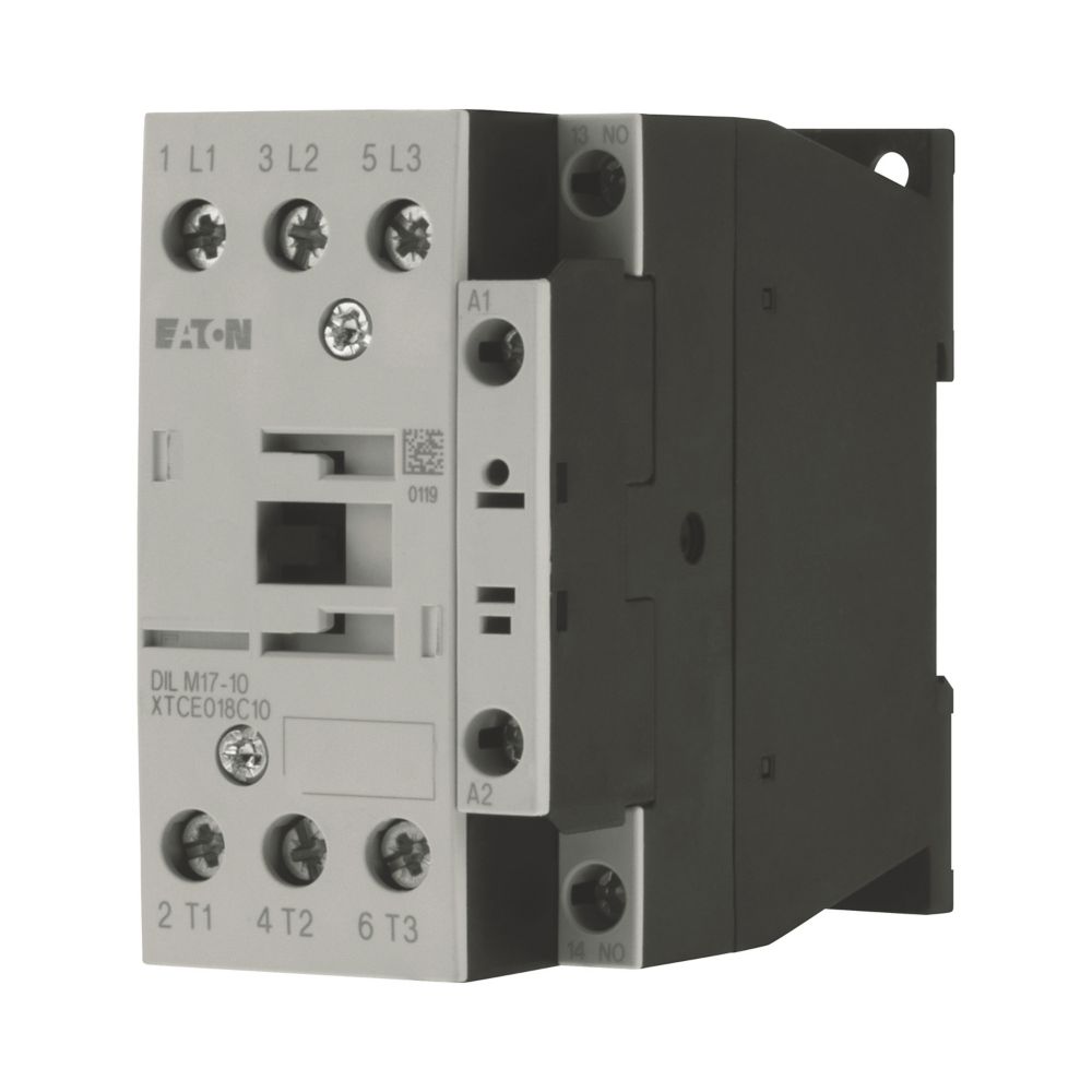
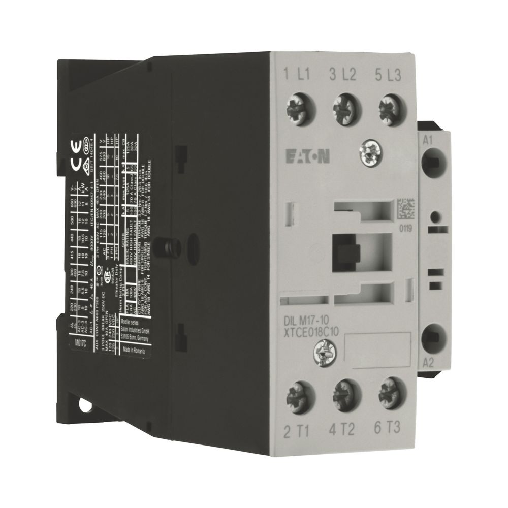
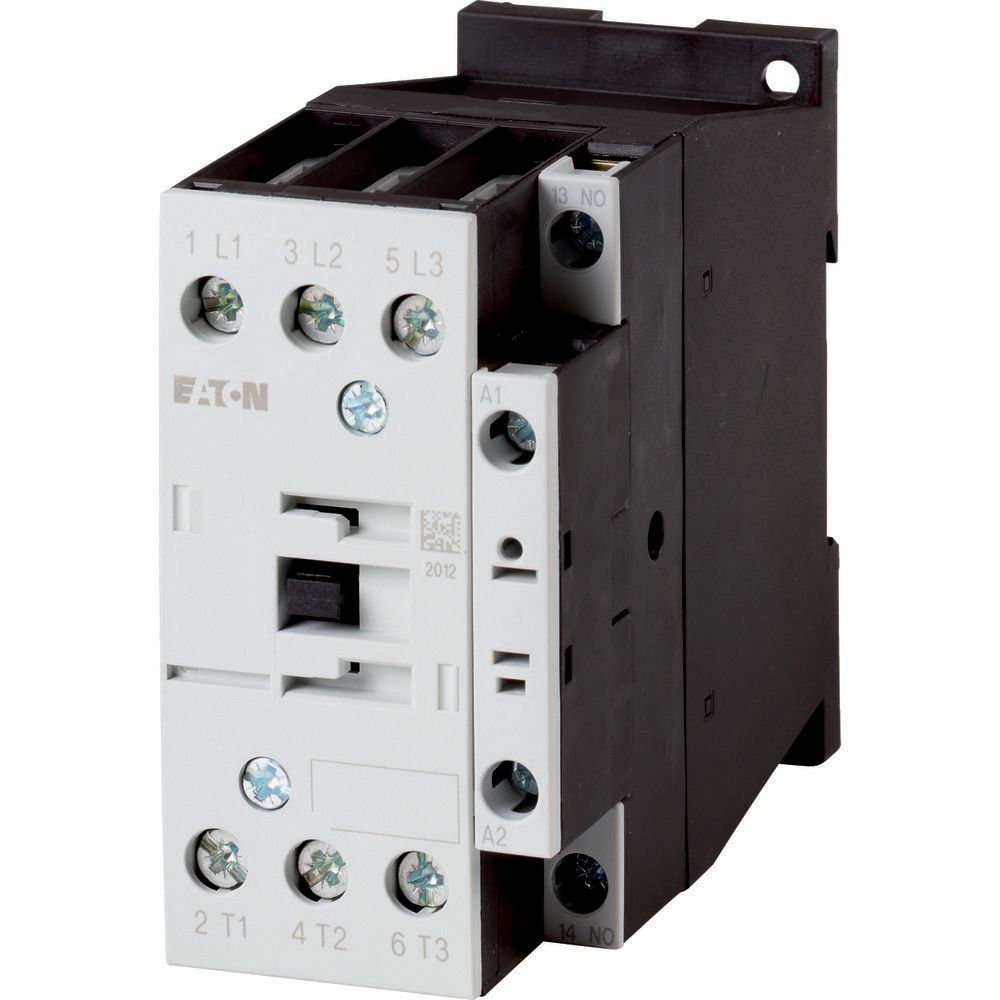
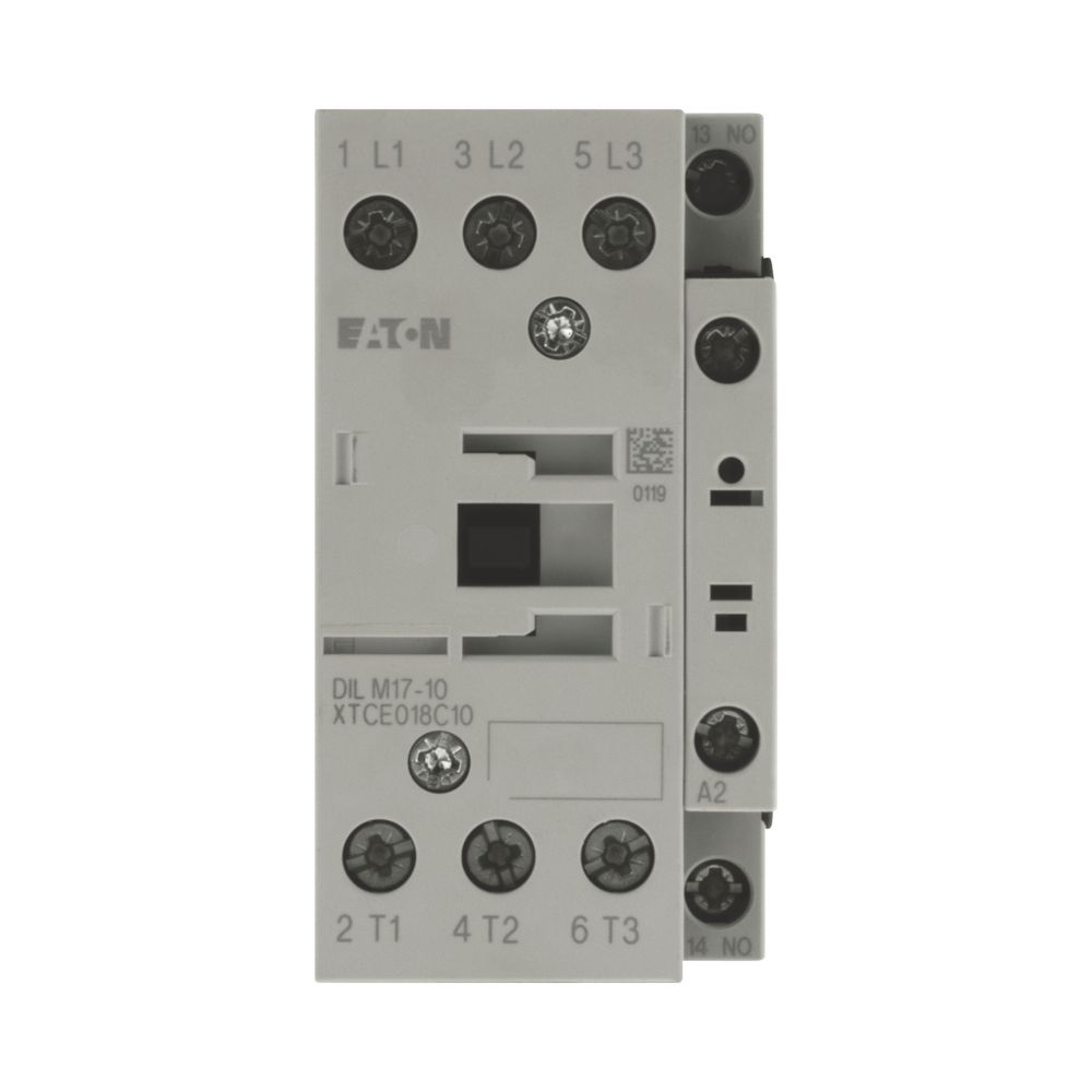
Product Name |
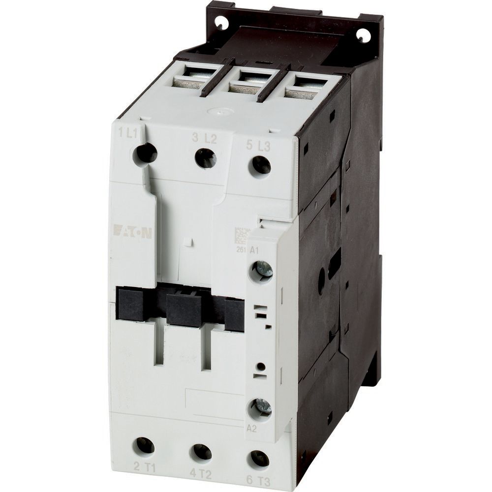
Eaton Moeller® series DILM contactor |
|
Catalog Number |
277018 |
|
Model Code |
DILM17-10(RDC24) |
|
EAN |
4015082770181 |
|
Product Length/Depth |
97 mm |
|
Product Height |
85 mm |
|
Product Width |
45 mm |
|
Product Weight |
0.534 kg |
|
Certifications |
UL 60947-4-1 UL CSA-C22.2 No. 60947-4-1-14 VDE 0660 IEC/EN 60947 UL Category Control No.: NLDX CSA CSA File No.: 012528 IEC/EN 60947-4-1 CSA Class No.: 2411-03, 3211-04 CE UL File No.: E29096 |
|
Catalog Notes |
Contacts according to EN 50012 |
| Product specifications |
Terminal capacity (flexible with ferrule) |
1 x (0.75 – 2.5) mm², Control circuit cables 1 x (0.75 – 16) mm², Main cables 2 x (0.75 – 10) mm², Main cables 2 x (0.75 – 2.5) mm², Control circuit cables |
|
Rated operational current for specified heat dissipation (In) |
18 A |
|
10.11 Short-circuit rating |
Is the panel builder’s responsibility. The specifications for the switchgear must be observed. |
|
Rated operational power at AC-3, 380/400 V, 50 Hz |
7.5 kW |
|
Conventional thermal current ith (3-pole, enclosed) |
32 A |
|
Rated operational power at AC-4, 380/400 V, 50 Hz |
4.5 kW |
|
Rated operational current (Ie) at AC-4, 440 V |
10 A |
|
Rated control supply voltage (Us) at AC, 50 Hz – min |
0 V |
|
Conventional thermal current ith at 60°C (3-pole, open) |
35 A |
|
10.4 Clearances and creepage distances |
Meets the product standard’s requirements. |
|
Number of contacts (normally closed) as main contact |
0 |
|
Short-circuit current rating (high fault at 480 V) |
125/70 A, Class J, max. Fuse, SCCR (UL/CSA) 50/32 A, max. CB, SCCR (UL/CSA) 10/100 kA, Fuse, SCCR (UL/CSA) 10/65 kA, CB, SCCR (UL/CSA) |
|
Conventional thermal current ith at 55°C (3-pole, open) |
37 A |
|
Rated operational power (NEMA) |
7.4 kW |
|
10.2.3.1 Verification of thermal stability of enclosures |
|
|
Ambient storage temperature – min |
40 °C |
|
Fitted with: |
Suppressor circuit in actuating electronics |
|
Rated breaking capacity at 380/400 V |
170 A |
|
Short-circuit current rating (basic rating) |
125 A, max. Fuse, SCCR (UL/CSA) 125 A, max. CB, SCCR (UL/CSA) 5 kA, SCCR (UL/CSA) |
|
Rated control supply voltage (Us) at AC, 50 Hz – max |
|
|
Rated breaking capacity at 660/690 V |
120 A |
|
Rated operational current (Ie) at DC-1, 220 V |
|
|
Special purpose rating of elevator control |
9.6 A, 240 V 60 Hz 3-ph, (UL/CSA) 10 HP, 600 V 60 Hz 3-ph, (UL/CSA) 11 A, 200 V 60 Hz 3-ph, (UL/CSA) 3 HP, 200 V 60 Hz 3-ph, (UL/CSA) 11 A, 480 V 60 Hz 3-ph, (UL/CSA) 7.5 HP, 480 V 60 Hz 3-ph, (UL/CSA) 11 A, 600 V 60 Hz 3-ph, (UL/CSA) 3 HP, 240 V 60 Hz 3-ph, (UL/CSA) |
|
Ambient operating temperature – max |
60 °C |
|
Assigned motor power at 115/120 V, 60 Hz, 1-phase |
2 HP |
|
Rated operational power at AC-4, 440 V, 50 Hz |
5.5 kW |
|
Electrical connection type of main circuit |
Screw connection |
|
Power consumption (sealing) at DC |
0.9 W |
|
Number Of Poles |
Three-pole |
|
Ambient operating temperature – min |
-25 °C |
|
10.6 Incorporation of switching devices and components |
Does not apply, since the entire switchgear needs to be evaluated. |
|
10.2.6 Mechanical impact |
|
|
10.3 Degree of protection of assemblies |
|
|
Application |
Contactors for Motors |
|
Operating frequency |
5000 mechanical Operations/h (DC operated) |
|
Voltage type |
DC |
|
Short-circuit protection rating (type 1 coordination) at 400 V |
63 A gG/gL |
|
Product category |
Contactors |
|
Rated operational current (Ie) at AC-4, 220 V, 230 V, 240 V |
|
|
Rated operational power at AC-3, 690 V, 50 Hz |
11 kW |
|
Heat dissipation capacity Pdiss |
0 W |
|
Assigned motor power at 460/480 V, 60 Hz, 3-phase |
10 HP |
|
Special purpose rating of tungsten incandescent lamps |
40 A, 480 V 60 Hz 3phase, 277 V 60 Hz 1phase, (UL/CSA) 40 A, 600 V 60 Hz 3phase, 347 V 60 Hz 1phase, (UL/CSA) |
|
Rated operational current (Ie) at AC-4, 500 V |
|
|
Rated operational power at AC-3, 240 V, 50 Hz |
|
|
Operating voltage at AC, 60 Hz – max |
690 V |
|
Terminal capacity (solid/stranded AWG) |
18 – 14, Control circuit cables Single 18 – 6, double 18 – 8, Main cables |
|
10.9.2 Power-frequency electric strength |
Is the panel builder’s responsibility. |
|
Degree of protection |
IP00 |
|
Overvoltage category |
III |
|
Ambient storage temperature – max |
80 °C |
|
Pollution degree |
3 |
|
Rated operational current (Ie) at AC-1, 380 V, 400 V, 415 V |
40 A |
|
Rated impulse withstand voltage (Uimp) |
8000 V AC |
|
Connection |
Screw terminals |
|
Operating voltage at AC, 60 Hz – min |
24 V |
|
Tightening torque |
1.2 Nm, Screw terminals, Control circuit cables 3.2 Nm, Screw terminals, Main cables |
|
Rated operational power at AC-4, 660/690 V, 50 Hz |
6.5 kW |
|
Frame size |
FS2 |
|
Conventional thermal current ith (1-pole, enclosed) |
80 A |
|
Rated operational current (Ie) at AC-3, 660 V, 690 V |
12 A |
|
10.2.2 Corrosion resistance |
|
|
10.2.4 Resistance to ultra-violet (UV) radiation |
|
|
10.2.7 Inscriptions |
|
|
Rated operational current (Ie) at AC-3, 380 V, 400 V, 415 V |
|
|
Number of contacts (normally open contacts) |
1 |
|
Short-circuit protection rating (type 2 coordination) at 400 V |
35 A gG/gL |
|
Special purpose rating of ballast electrical discharge lamps |
40 A (480V 60Hz 3phase, 277V 60Hz 1phase) 40 A (600V 60Hz 3phase, 347V 60Hz 1phase) |
|
Number of auxiliary contacts (normally open contacts) |
|
|
Special purpose rating of definite purpose rating |
18 A, FLA 480 V 60 Hz 3-ph, 100,000 cycles acc. to UL 1995, (UL/CSA) 108 A, LRA 480 V 60 Hz 3-ph, 100,000 cycles acc. to UL 1995, (UL/CSA) |
|
Rated operational power at AC-3, 500 V, 50 Hz |
12 kW |
|
Shock resistance |
10 g, N/O main contact, Mechanical, according to IEC/EN 60068-2-27, Half-sinusoidal shock 10 ms 5 g, N/C auxiliary contact, Mechanical, according to IEC/EN 60068-2-27, Half-sinusoidal shock 10 ms 5.3 g, N/O auxiliary contact, Mechanical, according to IEC/EN 60068-2-27 when tabletop-mounted, Half-sinusoidal shock 10 ms 6.9 g, N/O main contact, Mechanical, according to IEC/EN 60068-2-27 when tabletop-mounted, Half-sinusoidal shock 10 ms 7 g, N/O auxiliary contact, Mechanical, according to IEC/EN 60068-2-27, Half-sinusoidal shock 10 ms 3.5 g, N/C auxiliary contact, Mechanical, according to IEC/EN 60068-2-27 when tabletop-mounted, Half-sinusoidal shock 10 ms |
|
Rated operational current (Ie) at DC-1, 110 V |
|
|
Assigned motor power at 230/240 V, 60 Hz, 3-phase |
5 HP |
|
Drop-out voltage |
At least smoothed two-phase bridge rectifier or three-phase rectifier 0.6 – 0.15 x UC, DC operated |
|
Resistance per pole |
2.7 mΩ |
|
Ambient operating temperature (enclosed) – min |
25 °C |
|
Stripping length (control circuit cable) |
10 mm |
|
Operating voltage at AC, 50 Hz – max |
|
|
10.12 Electromagnetic compatibility |
|
|
Special purpose rating of refrigeration control (CSA only) |
40 A, FLA 480 V 60 Hz 3phase; (CSA) 180 A, LRA 600 V 60 Hz 3phase; (CSA) 30 A, FLA 600 V 60 Hz 3phase; (CSA) 240 A, LRA 480 V 60 Hz 3phase; (CSA) |
|
10.2.5 Lifting |
|
|
Stripping length (main cable) |
|
|
Ambient operating temperature (enclosed) – max |
|
|
Special purpose rating of resistance air heating |
40 A, 600 V 60 Hz 3phase, 347 V 60 Hz 1phase, (UL/CSA) 40 A, 480 V 60 Hz 3phase, 277 V 60 Hz 1phase, (UL/CSA) |
|
Rated control supply voltage (Us) at DC – min |
|
|
Short-circuit current rating (high fault at 600 V) |
125/70 A, Class J, max. Fuse, SCCR (UL/CSA) 10/22 kA, CB, SCCR (UL/CSA) 10/100 kA, Fuse, SCCR (UL/CSA) 50/32 A, max. CB, SCCR (UL/CSA) |
|
10.8 Connections for external conductors |
|
|
Number of main contacts (normally open contact) |
|
|
Rated breaking capacity at 220/230 V |
|
|
Screw size |
M3.5, Terminal screw, Control circuit cables M5, Terminal screw, Main cables |
|
Rated operational current (Ie) at AC-4, 400 V |
|
|
Short-circuit protection rating (type 2 coordination) at 690 V |
|
|
Assigned motor power at 575/600 V, 60 Hz, 3-phase |
15 HP |
|
Protection |
Finger and back-of-hand proof, Protection against direct contact when actuated from front (EN 50274) |
|
Rated operational power at AC-3, 440 V, 50 Hz |
10.5 kW |
|
Terminal capacity (stranded) |
1 x 16 mm², Main cables |
|
Rated breaking capacity at 500 V |
|
|
Rated operational power at AC-3, 415 V, 50 Hz |
10 kW |
|
Climatic proofing |
Damp heat, constant, to IEC 60068-2-78 Damp heat, cyclic, to IEC 60068-2-30 |
|
Emitted interference |
According to EN 60947-1 |
|
Connection to SmartWire-DT |
Yes In conjunction with DIL-SWD SmartWire DT contactor module |
|
Static heat dissipation, non-current-dependent Pvs |
|
|
Rated control supply voltage (Us) at DC – max |
27 V |
|
10.9.3 Impulse withstand voltage |
|
|
Utilization category |
AC-3: Normal AC induction motors: starting, switch off during running AC-4: Normal AC induction motors: starting, plugging, reversing, inching AC-1: Non-inductive or slightly inductive loads, resistance furnaces |
|
Rated operational current (Ie) at AC-3, 440 V |
|
|
10.5 Protection against electric shock |
|
|
Safe isolation |
440 V AC, Between coil and contacts, According to EN 61140 440 V AC, Between the contacts, According to EN 61140 |
|
Operating voltage at AC, 50 Hz – min |
|
|
10.13 Mechanical function |
The device meets the requirements, provided the information in the instruction leaflet (IL) is observed. |
|
10.9.4 Testing of enclosures made of insulating material |
|
|
Heat dissipation per pole, current-dependent Pvid |
0.7 W |
|
Actuating voltage |
RDC 24: 24 – 27 V DC |
|
Switching time (DC operated, make contacts, opening delay) – max |
30 ms |
|
Switching capacity (auxiliary contacts, general use) |
10 A, 600 V AC, (UL/CSA) 1 A, 250 V DC, (UL/CSA) |
|
Switching time (DC operated, make contacts, closing delay) – max |
47 ms |
|
Rated operational current (Ie) at AC-4, 660 V, 690 V |
8 A |
|
Equipment heat dissipation, current-dependent Pvid |
2.1 W |
|
Assigned motor power at 200/208 V, 60 Hz, 3-phase |
|
|
Pick-up voltage |
24 – 27 V DC (RDC 24) 0.7 – 1.2 V DC x Uc |
|
Suitable for |
Also motors with efficiency class IE3 |
|
Conventional thermal current ith at 40°C (3-pole, open) |
|
|
Terminal capacity (solid) |
1 x (0.75 – 16) mm², Main cables 2 x (0.75 – 2.5) mm², Control circuit cables 1 x (0.75 – 4) mm², Control circuit cables 2 x (0.75 – 10) mm², Main cables |
|
Number of auxiliary contacts (normally closed contacts) |
|
|
Interference immunity |
|
|
10.2.3.2 Verification of resistance of insulating materials to normal heat |
|
|
10.2.3.3 Resist. of insul. mat. to abnormal heat/fire by internal elect. effects |
|
|
Lifespan, mechanical |
10,000,000 Operations (DC operated) |
|
Short-circuit protection rating (type 1 coordination) at 690 V |
50 A gG/gL |
|
Rated making capacity up to 690 V (cos phi to IEC/EN 60947) |
238 A |
|
Rated operational power at AC-4, 240 V, 50 Hz |
3 kW |
|
Rated operational power at AC-4, 500 V, 50 Hz |
6 kW |
|
Rated operational current (Ie) at DC-1, 60 V |
|
|
Rated operational power at AC-4, 220/230 V, 50 Hz |
2.5 kW |
|
Rated operational voltage (Ue) at AC – max |
|
|
Rated control supply voltage (Us) at AC, 60 Hz – min |
|
|
10.7 Internal electrical circuits and connections |
|
|
Power consumption (pick-up) at DC |
12 W |
|
10.10 Temperature rise |
The panel builder is responsible for the temperature rise calculation. Eaton will provide heat dissipation data for the devices. |
|
Switching capacity (main contacts, general use) |
40 A, Maximum motor rating (UL/CSA) |
|
Conventional thermal current ith at 50°C (3-pole, open) |
38 A |
|
Rated operational current (Ie) at AC-3, 500 V |
|
|
Assigned motor power at 230/240 V, 60 Hz, 1-phase |
3 HP |
|
Screwdriver size |
0.8 x 5.5/1 x 6 mm, Terminal screw, Standard screwdriver 2, Terminal screw, Pozidriv screwdriver |
|
Duty factor |
100 % |
|
Rated operational current (Ie) at AC-3, 220 V, 230 V, 240 V |
|
|
Conventional thermal current ith of main contacts (1-pole, open) |
88 A |
|
Rated control supply voltage (Us) at AC, 60 Hz – max |
|
|
Arcing time |
10 ms |
|
Rated operational power at AC-4, 415 V, 50 Hz |
5 kW |
|
Switching capacity (auxiliary contacts, pilot duty) |
A600, AC operated (UL/CSA) P300, DC operated (UL/CSA) |
|
Rated insulation voltage (Ui) |
|
|
Altitude |
Max. 2000 m |
| Catalogs |
Product Range Catalog Switching and protecting motors |
|
|
SmartWire-DT Catalog |
|
|
Product overview for machinery |
|
|
Switching and protecting motors – catalog |
|
| Certification reports |
0000SPC-571 |
|
| Characteristic curve |
eaton-contactors-component-dilm-characteristic-curve-003.eps |
|
|
2100DIA-7 |
|
|
210U038 |
|
|
2100DIA-8 |
|
|
eaton-contactors-switch-dilm-characteristic-curve.eps |
|
|
eaton-contactors-short-time-loading-dilm-characteristic-curve.eps |
|
|
eaton-contactors-switch-dilm-characteristic-curve-002.eps |
|
|
210U039 |
|
| Drawings |
eaton-contactors-mounting-dilm-dimensions-002.eps |
|
|
eaton-contactors-contact-dilm-dimensions-002.eps |
|
|
210N018 |
|
|
eaton-contactors-dilm-dimensions.eps |
|
|
210X202 |
|
|
eaton-contactors-mounting-dilm-dimensions.eps |
|
|
210N017 |
|
|
210T014 |
|
|
eaton-contactors-dilm-3d-drawing-009.eps |
|
|
210I192 |
|
|
eaton-general-ie-ready-dilm-contactor-standards.eps |
|
| eCAD model |
DA-CE-ETN.DILM17-10(RDC24) |
|
| Installation instructions |
IL03407014Z2018_07 |
|
|
IL03407014Z |
|
| mCAD model |
DA-CS-dil_m17_38 |
|
|
DA-CD-dil_m17_38 |
|
| PEP Eco-passport |
EATO-00026-V01.01-EN |
|
| Specifications and datasheets |
Eaton Specification Sheet – 277018 |
|
| System overview |
210O154 |
|
|
eaton-contactors-dilm-contactor-system-overview.eps |
|
| Wiring diagrams |
eaton-contactors-contact-dilm-wiring-diagram.eps |
|
|
210S026 |
|
| Date |
Thu Jul 20 2023 |
|