| General specifications |
Product Name |
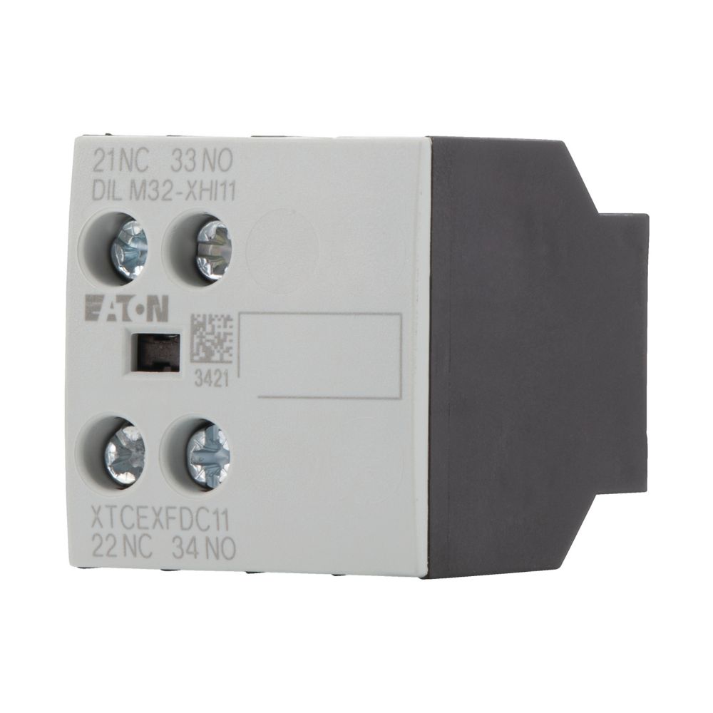
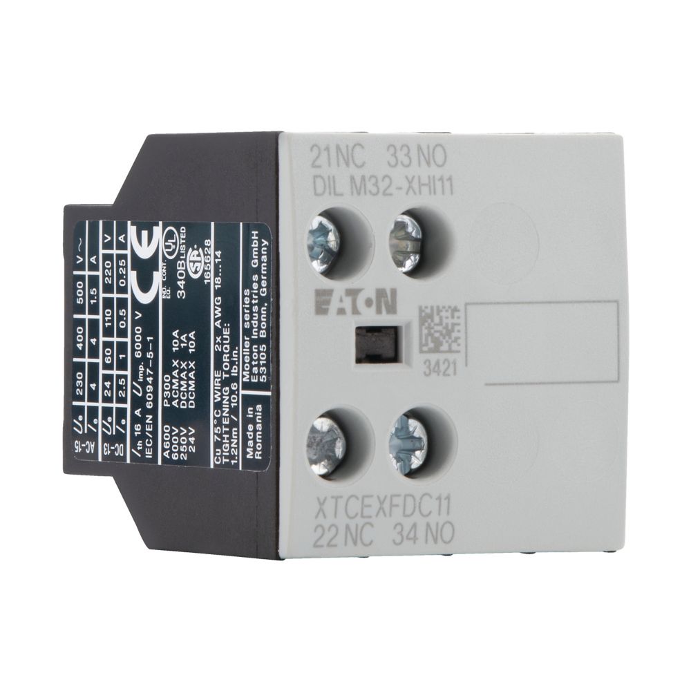
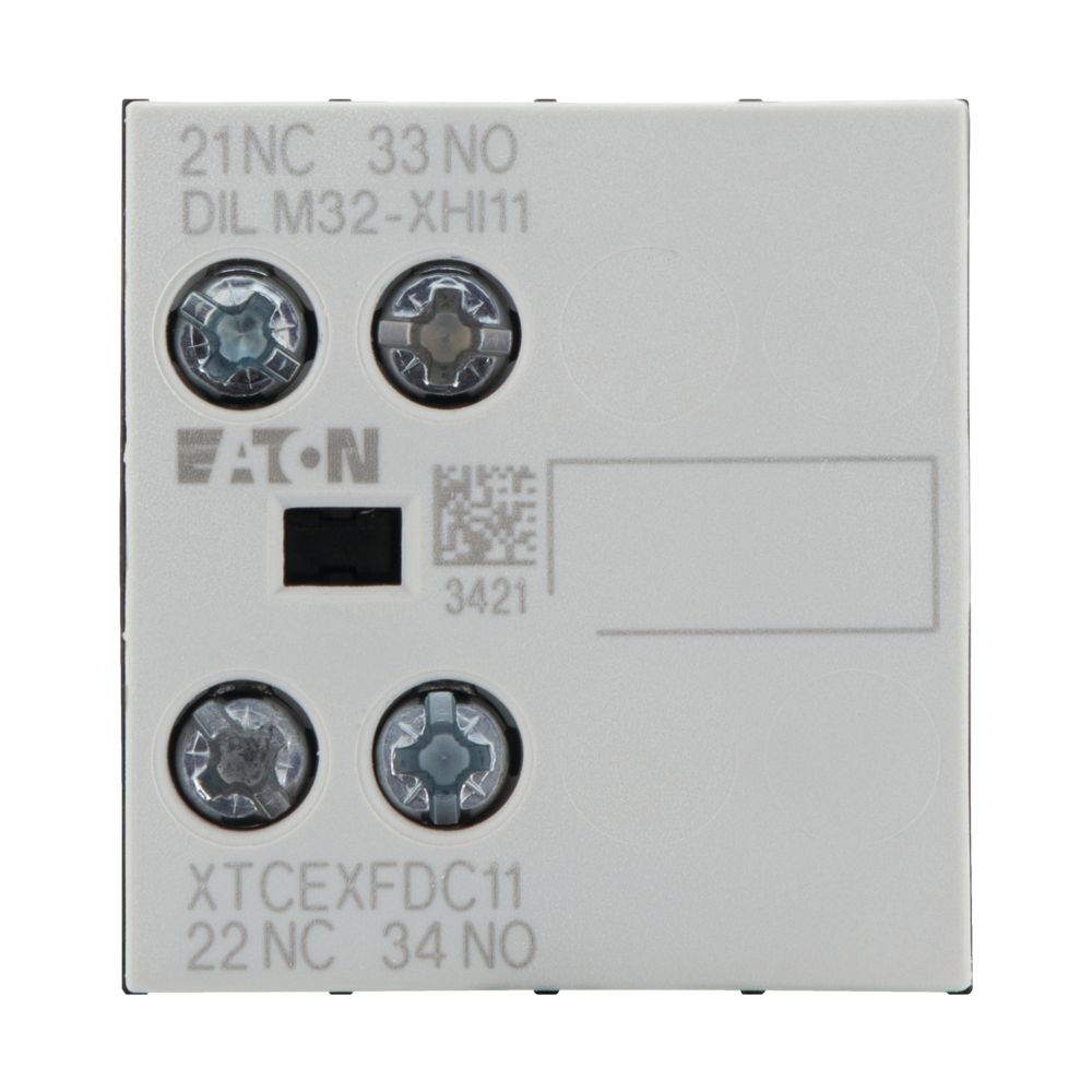
Eaton Moeller® series DILM auxiliary contact module |
|
Catalog Number |
277376 |
|
Model Code |
DILM32-XHI11 |
|
EAN |
4015082773762 |
|
Product Length/Depth |
45 mm |
|
Product Height |
38 mm |
|
Product Width |
36 mm |
|
Product Weight |
0.038 kg |
|
Certifications |
UL 508 VDE 0660 CE CSA UL IEC/EN 60947-4-1 CSA-C22.2 No. 14-05 IEC/EN 60947 CSA Class No.: 3211-03 CSA File No.: 012528 UL Category Control No.: NKCR UL File No.: E29184 |
| Product specifications |
Rated operational current for specified heat dissipation (In) |
4 A |
|
Terminal capacity (flexible with ferrule) |
1 x (0.75 – 2.5) mm² 2 x (0.75 – 2.5) mm² |
|
10.11 Short-circuit rating |
Is the panel builder’s responsibility. The specifications for the switchgear must be observed. |
|
Ambient operating temperature (enclosed) – min |
25 °C |
|
Lamp holder |
None |
|
10.4 Clearances and creepage distances |
Meets the product standard’s requirements. |
|
10.12 Electromagnetic compatibility |
|
|
Mounting method |
Front fastening |
|
10.2.5 Lifting |
Does not apply, since the entire switchgear needs to be evaluated. |
|
Ambient operating temperature (enclosed) – max |
40 °C |
|
10.2.3.1 Verification of thermal stability of enclosures |
|
|
Ambient storage temperature – min |
|
|
Fitted with: |
Interlocked opposing contacts |
|
10.8 Connections for external conductors |
Is the panel builder’s responsibility. |
|
Protection |
Finger and back-of-hand proof, Protection against direct contact when actuated from front (EN 50274) |
|
Ambient operating temperature – max |
60 °C |
|
Climatic proofing |
Damp heat, constant, to IEC 60068-2-78 Damp heat, cyclic, to IEC 60068-2-30 |
|
Features |
Interlocked opposing contacts within an auxiliary contact module (according to IEC 60947-5-1 Annex L) |
|
Lifespan, electrical |
1,300,000 Operations (at 230 V, AC-15, 3 A) |
|
Static heat dissipation, non-current-dependent Pvs |
0 W |
|
Rated operational current (Ie) at AC-15, 500 V |
1.5 A |
|
10.9.3 Impulse withstand voltage |
|
|
Number of poles |
Two-pole |
|
Ambient operating temperature – min |
-25 °C |
|
10.6 Incorporation of switching devices and components |
|
|
10.5 Protection against electric shock |
|
|
Safe isolation |
400 V AC, Between coil and auxiliary contacts, According to EN 61140 400 V AC, Between auxiliary contacts, According to EN 61140 |
|
Rated operational current (Ie) at AC-15, 220 V, 230 V, 240 V |
6 A |
|
Electric connection type |
Screw connection |
|
10.13 Mechanical function |
The device meets the requirements, provided the information in the instruction leaflet (IL) is observed. |
|
10.2.6 Mechanical impact |
|
|
10.9.4 Testing of enclosures made of insulating material |
|
|
Number of contacts (normally closed contacts) |
1 |
|
10.3 Degree of protection of assemblies |
|
|
Heat dissipation per pole, current-dependent Pvid |
0.16 W |
|
Rated operational current (Ie) at AC-15, 380 V, 400 V, 415 V |
|
|
Switching capacity (auxiliary contacts, general use) |
1 A, 250 V DC, (UL/CSA) 10 A, 600 V AC, (UL/CSA) |
|
Number of switches (fault signal) |
0 |
|
Equipment heat dissipation, current-dependent Pvid |
|
|
Heat dissipation capacity Pdiss |
|
|
Rated operational current (Ie) at DC-13, 60 V |
1 A |
|
Conventional thermal current ith at 60°C (3-pole, open) |
16 A |
|
Rated operational current (Ie) |
3 A at 110 V, DC L/R ≤ 15 ms (with 1 contact in series) 10 A at 24 V, DC L/R ≤ 15 ms (with 1 contact in series) 6 A at 60 V, DC L/R ≤ 15 ms (with 1 contact in series) 1 A at 220 V, DC L/R ≤ 15 ms (with 1 contact in series) |
|
Short-circuit protection rating without welding |
10 A gG/gL, 500 V, Max. Fuse, Contacts |
|
Terminal capacity (solid) |
|
|
10.2.3.2 Verification of resistance of insulating materials to normal heat |
|
|
10.2.3.3 Resist. of insul. mat. to abnormal heat/fire by internal elect. effects |
|
|
Connection type |
|
|
Rated operational current (Ie) at DC-13, 220 V, 230 V |
0.25 A |
|
Terminal capacity (solid/stranded AWG) |
18 – 14 |
|
10.9.2 Power-frequency electric strength |
|
|
Control circuit reliability |
< 2 λ, < 1 failure at 100,000,000 Operations (at Uₑ = 24 V DC, Umin = 17 V, Imin = 5.4 mA) |
|
Overvoltage category |
III |
|
Degree of protection |
IP20 |
|
Ambient storage temperature – max |
80 °C |
|
Rated operational voltage (Ue) at AC – max |
500 V |
|
Pollution degree |
3 |
|
10.7 Internal electrical circuits and connections |
|
|
Rated impulse withstand voltage (Uimp) |
6000 V AC |
|
10.10 Temperature rise |
The panel builder is responsible for the temperature rise calculation. Eaton will provide heat dissipation data for the devices. |
|
Functions |
For standard applications |
|
Tightening torque |
1.2 Nm, Screw terminals |
|
Screwdriver size |
0.8 x 5.5/1 x 6 mm, Terminal screw, Standard screwdriver 2, Terminal screw, Pozidriv screwdriver |
|
Type |
Front mounting auxiliary contact |
|
10.2.2 Corrosion resistance |
|
|
10.2.4 Resistance to ultra-violet (UV) radiation |
|
|
10.2.7 Inscriptions |
|
|
Number of contacts (normally open contacts) |
|
|
Short-circuit protection rating |
Max. 10 A gG/gL, Fuse, Without welding, Auxiliary contacts |
|
Model |
Top mounting |
|
Rated operational current (Ie) at DC-13, 110 V |
0.5 A |
|
Number of contacts (change-over contacts) |
|
|
Shock resistance |
5 g, N/C auxiliary contact, Mechanical, according to IEC/EN 60068-2-27, Half-sinusoidal shock 10 ms 7 g, N/O auxiliary contact, Mechanical, according to IEC/EN 60068-2-27, Half-sinusoidal shock 10 ms |
|
Switching capacity (auxiliary contacts, pilot duty) |
P300, DC operated (UL/CSA) A600, AC operated (UL/CSA) |
|
Rated insulation voltage (Ui) |
690 V |
|
Rated operational current (Ie) at DC-13, 24 V |
2.5 A |
| Catalogs |
Switching and protecting motors – catalog |
|
|
SmartWire-DT Catalog |
|
|
Product Range Catalog Switching and protecting motors |
|
|
Product overview for machinery |
|
| Certification reports |
DA-DC-00004110.pdf |
|
|
DA-DC-00004246.pdf |
|
|
DA-DC-00004109.pdf |
|
|
DA-DC-00004245.pdf |
|
| Drawings |
eaton-contactors-module-dilm-dimensions.eps |
|
|
eaton-contactors-frame-dilm-dimensions.eps |
|
|
210T013 |
|
|
2110DIM-1 |
|
|
210I104 |
|
|
eaton-contactors-contact-dilm-accessory-3d-drawing.eps |
|
| eCAD model |
ETN.DILM32-XHI11 |
|
| Installation instructions |
IL03407013Z |
|
| mCAD model |
dil_m32_xhi_2 |
|
|
dil_m32_xhi_2.stp |
|
| Specifications and datasheets |
Eaton Specification Sheet – 277376 |
|
| Wiring diagrams |
210S030 |
|
|
2100SWI-119 |
|
|
eaton-contactors-contact-sdainl-combination-wiring-diagram.eps |
|
| Date |
Thu Jul 20 2023 |
|