Description
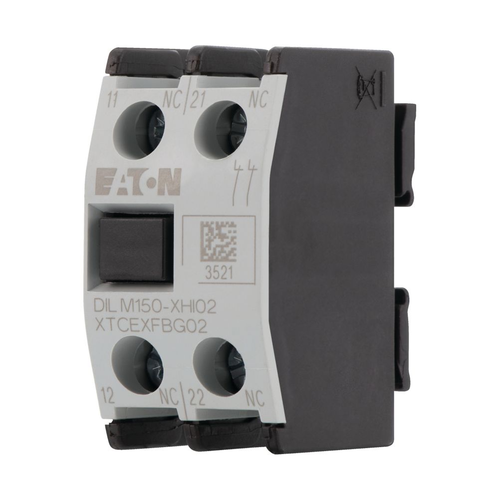
General specifications Product Name Eaton Moeller® series DILM auxiliary contact module
Catalog Number277946
Model CodeDILM150-XHI11
UPC782116354771
EAN4015082779467
Product Length/Depth39 mm
Product Height46 mm
Product Width24 mm
Product Weight0.03 kg
CertificationsIEC/EN 60947-4-1 CE CSA UL Category Control No.: NKCR CSA-C22.2 No. 14-05 VDE 0660 UL CSA File No.: 012528 IEC/EN 60947 CSA Class No.: 3211-03 UL 508 UL File No.: E29184
Product specifications Rated operational current for specified heat dissipation (In) 4 A
Terminal capacity (flexible with ferrule)1 x (0.75 – 2.5) mm² 2 x (0.75 – 2.5) mm²
10.11 Short-circuit ratingIs the panel builder’s responsibility. The specifications for the switchgear must be observed.
Ambient operating temperature (enclosed) – min25 °C
Lamp holderNone
10.4 Clearances and creepage distancesMeets the product standard’s requirements.
10.12 Electromagnetic compatibility
Mounting methodFront fastening
10.2.5 LiftingDoes not apply, since the entire switchgear needs to be evaluated.
Ambient operating temperature (enclosed) – max40 °C
10.2.3.1 Verification of thermal stability of enclosures
Ambient storage temperature – min
Fitted with:Interlocked opposing contacts
10.8 Connections for external conductorsIs the panel builder’s responsibility.
ProtectionFinger and back-of-hand proof, Protection against direct contact when actuated from front (EN 50274)
Ambient operating temperature – max60 °C
Climatic proofingDamp heat, cyclic, to IEC 60068-2-30 Damp heat, constant, to IEC 60068-2-78
FeaturesInterlocked opposing contacts within an auxiliary contact module (according to IEC 60947-5-1 Annex L)
Lifespan, electrical1,300,000 Operations (at 230 V, AC-15, 3 A)
Static heat dissipation, non-current-dependent Pvs0 W
Rated operational current (Ie) at AC-15, 500 V1.5 A
10.9.3 Impulse withstand voltage
Number of polesTwo-pole
Ambient operating temperature – min-25 °C
10.6 Incorporation of switching devices and components
10.5 Protection against electric shock
Safe isolation440 V AC, Between auxiliary contacts, According to EN 61140 440 V AC, Between coil and auxiliary contacts, According to EN 61140
Rated operational current (Ie) at AC-15, 220 V, 230 V, 240 V6 A
Electric connection typeScrew connection
10.13 Mechanical functionThe device meets the requirements, provided the information in the instruction leaflet (IL) is observed.
10.2.6 Mechanical impact
10.9.4 Testing of enclosures made of insulating material
Number of contacts (normally closed contacts)1
10.3 Degree of protection of assemblies
Heat dissipation per pole, current-dependent Pvid0.23 W
Rated operational current (Ie) at AC-15, 380 V, 400 V, 415 V
Switching capacity (auxiliary contacts, general use)15 A, 600 V AC, (UL/CSA) 1 A, 250 V DC, (UL/CSA)
Number of switches (fault signal)0
Equipment heat dissipation, current-dependent Pvid
Heat dissipation capacity Pdiss
Conventional thermal current ith at 60°C (3-pole, open)16 A
Rated operational current (Ie)6 A at 60 V, DC L/R ≤ 15 ms (with 1 contact in series) 3 A at 110 V, DC L/R ≤ 15 ms (with 1 contact in series) 1 A at 220 V, DC L/R ≤ 15 ms (with 1 contact in series) 10 A at 24 V, DC L/R ≤ 15 ms (with 1 contact in series)
Short-circuit protection rating without welding16 A gG/gL, 500 V, Max. Fuse, Contacts
Terminal capacity (solid)
10.2.3.2 Verification of resistance of insulating materials to normal heat
10.2.3.3 Resist. of insul. mat. to abnormal heat/fire by internal elect. effects
Connection type
Terminal capacity (solid/stranded AWG)18 – 14
10.9.2 Power-frequency electric strength
Control circuit reliability< 2 λ, < 1 failure at 100,000,000 Operations (at Uₑ = 24 V DC, Umin = 17 V, Imin = 5.4 mA)
Overvoltage categoryIII
Degree of protectionIP20
Ambient storage temperature – max80 °C
Rated operational voltage (Ue) at AC – max500 V
Pollution degree3
10.7 Internal electrical circuits and connections
Rated impulse withstand voltage (Uimp)6000 V AC
10.10 Temperature riseThe panel builder is responsible for the temperature rise calculation. Eaton will provide heat dissipation data for the devices.
FunctionsFor standard applications
Tightening torque1.2 Nm, Screw terminals
Screwdriver size0.8 x 5.5/1 x 6 mm, Terminal screw, Standard screwdriver 2, Terminal screw, Pozidriv screwdriver
TypeFront mounting auxiliary contact
10.2.2 Corrosion resistance
10.2.4 Resistance to ultra-violet (UV) radiation
10.2.7 Inscriptions
Number of contacts (normally open contacts)
Short-circuit protection ratingMax. 16 A gG/gL, Fuse, Without welding, Auxiliary contacts
ModelTop mounting
Number of contacts (change-over contacts)
Shock resistance5 g, N/C auxiliary contact, Mechanical, according to IEC/EN 60068-2-27, Half-sinusoidal shock 10 ms 7 g, N/O auxiliary contact, Mechanical, according to IEC/EN 60068-2-27, Half-sinusoidal shock 10 ms
Switching capacity (auxiliary contacts, pilot duty)P300, DC operated (UL/CSA) A600, AC operated (UL/CSA)
Rated insulation voltage (Ui)690 V
Catalogs Switching and protecting motors – catalog
SmartWire-DT Catalog
Product Range Catalog Switching and protecting motors
Product overview for machinery
Certification reports DA-DC-00004070.pdf
DA-DC-00004229.pdf
Drawings 210I182
eaton-contactors-contact-dilm-accessory-3d-drawing-003.eps
eCAD model ETN.DILM150-XHI11
Installation instructions IL03407034Z
mCAD model dil_m150_xhi_2
dil_m150_xhi_2.stp
Specifications and datasheets Eaton Specification Sheet – 277946
Wiring diagrams 210S154
eaton-contactors-contact-dilm-accessory-wiring-diagram-004.eps
2100SWI-131
DateThu Jul 20 2023