Description
Product Overview
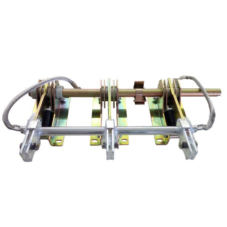
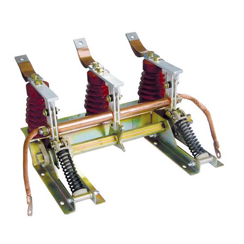
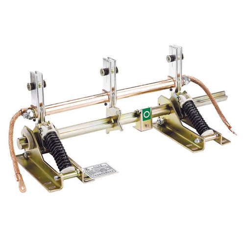
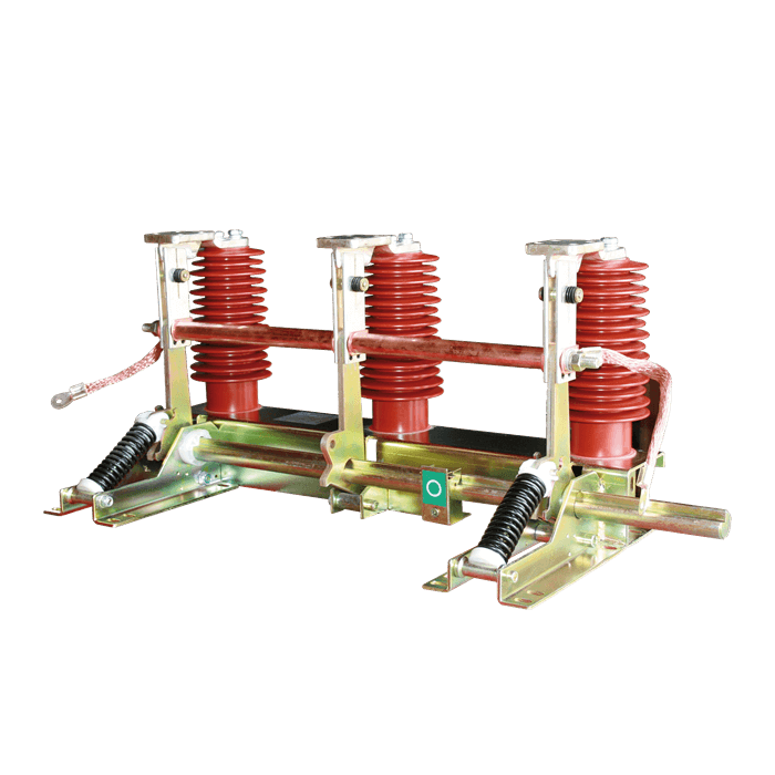
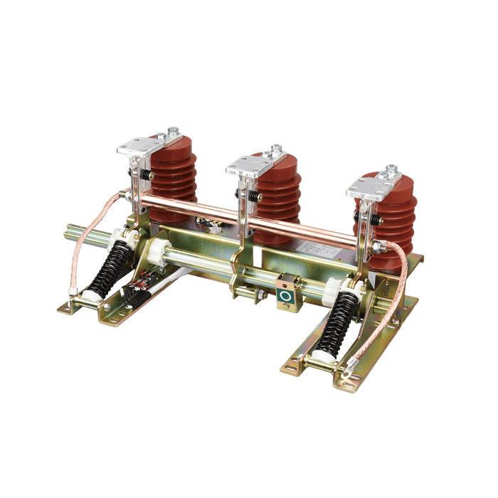
JN15-12/D15-80 electric earthing switch is researched and developed independently by our company with refers to the current state stand and IEC stand, its electric operating mechanism is combined with the earthing switch, and the installation result of the earthing switch is not changed. it has the advantage of a reasonable design, reliable electrical and mechanical properties, and convenient installation and maintenance. At present, it has passed all types of tests in the mechanical industry high-voltage electrical products quality testing center
Main Features
1, The installation is simple. it is combined with the earthing switch body and it is unnecessary to change the installation structure of the original earthing switch.
2. It may realize free switching over of manual operation and electric operation
3. It is safe and reliable: The anti-motor-locking function may realize the control and protection of the motor
Overall Dimensions and installing Dimensions of JN15-12/D1.5-80 Earthing Switch

Ordering Instruction
1. Whether an auxiliary switch is required and whether the auxiliary switch is required to be ed to the terminal. The auxiliary switch shall not exceed four
open and closed independent contacts.
2. Because the mechanism is on the right, the open and closing indicators of the right and left operation (the direction of the long axis extended) both are installed on the left.
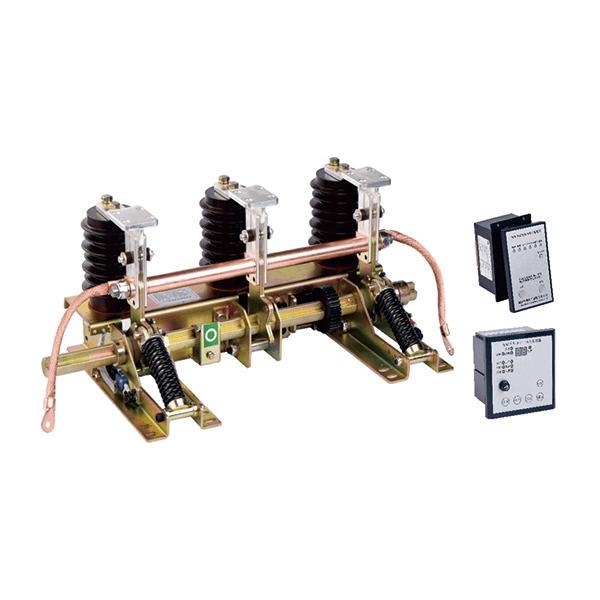
3, Indicate the operation mode of the electrics switch is crank arm drive or bevel aear.4. Available choices of the electric control device:(1)ERC-10-HB-A1, HB-KZ-J(Panel type)installs on the instrument door, (2) ERC-20HB-A1, HB-KZ-J (Rail type)installs on track of instrument indoor. (3) TERC-20-HB-A1 handcart and earthing knife-switch is two-in-one, installs on track of instrument.
Control Circuit and Connection of Electric Earthing Switch ( ERC-10-HB-A1)

Description of Electric Connection of Electric Earthing Switch
1. When terminals No.3 & 4 of an electric control device for switchgear are connected correspondingly to the positive and negative poles of terminals No.1 & 2 of an electric earthing switch, the polarity of the power supply shall not be reversed to prevent the motor being damaged. When powering on tor debugging, observe whether the rotation direction of the big operating shaft gear of the earthing switch is consistent with the on/off state of the switch: if not it is necessary to reverse the positive and negative poles of the terminal.
2. If the electric earthing switch (before being installed in the cabinet) is to be trial-operated separately, terminal No.11 of the electric control device for switchgear shall be short-circuited to terminal No.9 (0V common terminal).
3. terminals No.12&13 of the electric control device of the switchgear are short-connected with the common end of the switching input and are
in the remote operation state effectively.
4. The terminal No.10 of the electric control device of the switchgear is valid at a distance when it is short-connected with the input of the switching quantity.
If you need a quote or more information about this product, please send us a message and we will get back to you within 1 working day.
Please select the method below:
Message Form
Mobile/Whatsapp: +8613396988128
Linkedin