Description
Product Overview
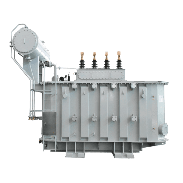
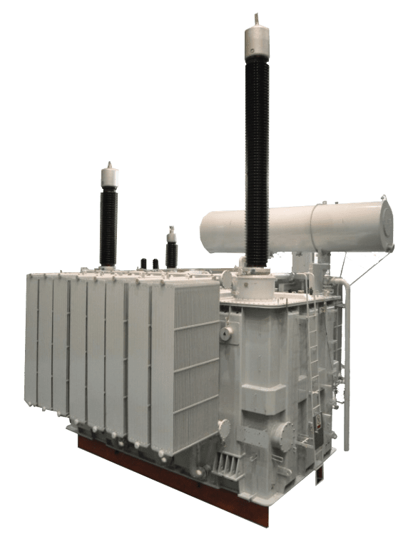
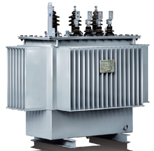
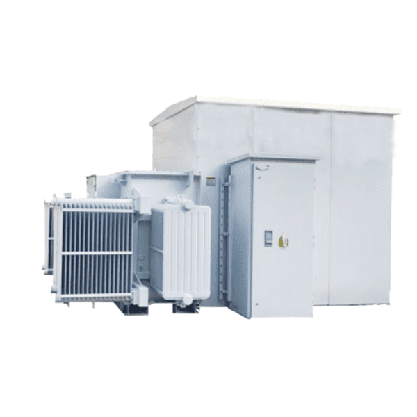
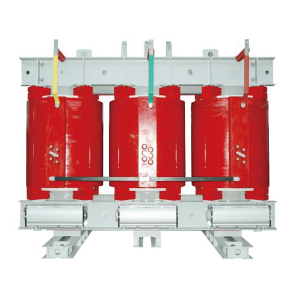
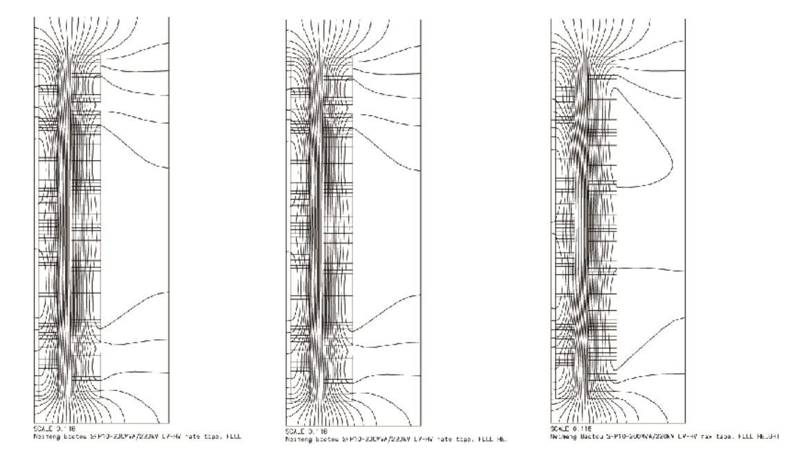
35-500kV series oil immersed power transformer has optimized design using advanced technologies, in order to offer low noise,low loss low partial discharge, high short circuit withstand capability. Advance design software are used for electromagnetic calculation and design of transformer, while 3-D,2-D CAD software for structural design ensure sufficient safety margin during short circuit period. This is based on in-depth theoretical and experimental studies on magnetic ,thermal, mechanical strength and short circuit strength. To ensure reliability of the transformer, the insulation are decided based on calculation on main and vertical insulations. The accurate calculation of the electric filed distribution in inner coils will ensure voltage gradient and at coil end it will ensure low partial discharge.
Product Features
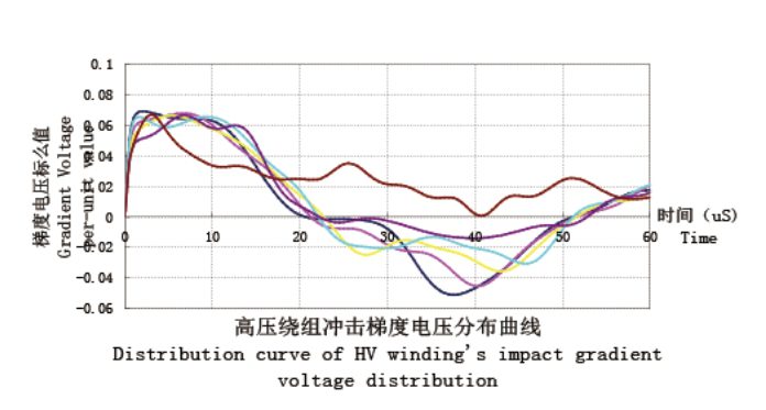
Potential distribution is effectively improved by application of software to calculate the impact and gradient potential distribution.The potential calculation is also done between various parts of the coil including between the coil and coi land earthing.
Low Noise
- Select high-quality core materials and appropriate magnetic flux density and self-vibration frequency of the core.
- Adopt a high-precision Jog line with step shearing and automatic stacking functions to reduce burrs on silicon steel sheets.
- The core stacking adopts the “stepped full-slope step lap joint technology” to improve the magnetic flux distribution at the joint.
- Use PET tape to evenly bind the core to reduce core vibration.
- The whole core is “soft-connected” with the oil tank to reduce the transmission of the noise of the transformer body to the oil tank.
Low Temperature Rise
- Calculate the oil flow distribution and adopt a reasonable oil flow distribution structure to reduce the hot spot temperature rise and average temperature rise of the winding.
- Set axial oil ducts in the windings of large-capacity transformers.
- Control the transverse eddy current loss of the winding.
Low Loss
- Adopt leakage magnetic calculation and take effective measures to reduce stray loss, effectively prevent local overheating, and reduce the hot spot temperature rise of the winding.
- Reasonably select coil conductors to reduce additional losses such as winding eddy current loss and stray loss.
- Optimize the transposition between parallel conductors to make the interlinking magnetic flux uniform and reduce the circulating current loss caused by leakage magnetic field.
- Adopt a new type of magnetic shielding structure to reduce the stray loss of structural parts and prevent local overheating.
- Implement slotting processing on the small core laminations to reduce the loss of core structural parts and prevent local overheating.
Low Partial Discharge and Extended Service Life
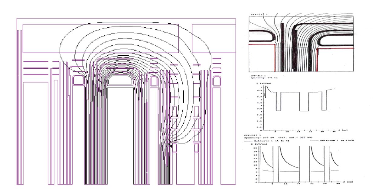
- Analytically calculate the electric field to improve the areas with concentrated electric field.
- By using a special adhesive and vacuum oil injection after the transformer is fully assembled, effectively prevent the formation of bubbles in the insulation parts and inside the transformer, thereby reducing partial discharge.
- Core manufacturing, coil winding, transformer body assembly, final assembly, and testing are all carried out in a fully air-conditioned, fully enclosed, and dust-free purification workshop, effectively controlling foreign matters from entering the transformer body. At the same time, the connection of leads is carried out by crimping method (different from the commonly used welding method) to reduce partial discharge.
High Seismic Resistance
- The bushing design adopts the dynamic design method, with a horizontal acceleration of 0.5g and a waveform of the resonant sinusoidal third harmonic, and the loading position is at the lower end of the bushing flange seat. The transformer body adopts the static design method, with a static horizontal acceleration of 0.5g.
Good Mechanical Strength of Transformer
- Eliminate the weak points of structural parts strength through software simulation calculation to improve the mechanical strength of structural parts.
- Manufactured with high-strength steel plates.
- Processed with laser cutting equipment, with small deformation and stress of structural parts.
High Short-Circuit Resistance
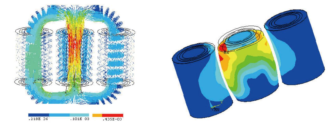
- Adopt the dynamic analysis method to calculate the short-circuit mechanical force.
- The low-voltage side adopts self-bonding transposed conductors, effectively increasing the short-circuit resistance.
- The winding is wound by a vertical winding machine or a horizontal winding machine with a tensioning device, and the inner liner is a hard paper tube.
- The conductor transposition adopts a hydraulic transposition tool.
- The transformer body adopts constant pressure drying and integral assembly, and the integral assembly adopts thermal shrink fitting.
Quality Warranty
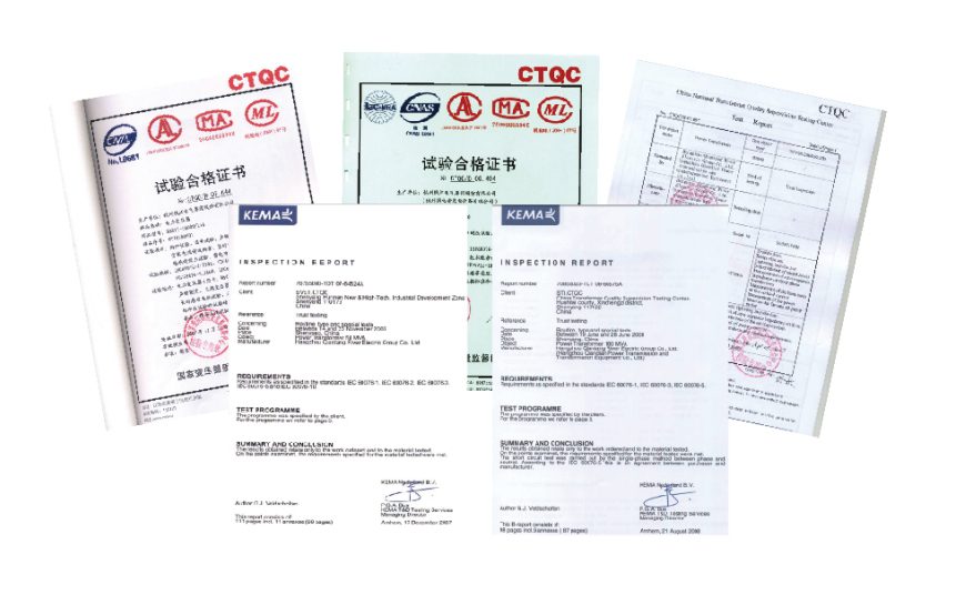
In May 2002, the SZ9 – 40MVA / 110kV transformer successfully passed the dynamic short-circuit test carried out at the National Transformer Quality Supervision and Inspection Center.
In August 2003, the SZ10 – 31500 / 220kV transformer successfully passed the witnessed test carried out at the National Transformer Quality Supervision and Inspection Center.
In March 2007, the SFP10 – 200000 / 220kV transformer successfully passed the witnessed test carried out at the National Transformer Quality Supervision and Inspection Center.
In December 2007, the SZ11 – 50000 / 110kV transformer successfully passed the dynamic short-circuit test carried out at the National Transformer Quality Supervision and Inspection Center and witnessed by KEMA of the Netherlands.
In July 2008, the SFPSZ11 – 180000 / 220kV transformer successfully passed the witnessed test carried out at the National Transformer Quality Supervision and Inspection Center.
In August 2008, the SFPSZ11 – 180000 / 220kV transformer successfully passed the dynamic short-circuit test carried out at the National Transformer Quality Supervision and Inspection Center and witnessed by KEMA of the Netherlands.
In January 2010, the SSZ11 – 180000 / 220kV transformer successfully passed the witnessed test carried out at the Machinery Industry Transformer Product Quality Supervision and Inspection Center.
In September 2010, the SSZ11 – 180000 / 220kV transformer successfully passed the witnessed test carried out at the National Transformer Quality Supervision and Inspection Center and the Transformer Laboratory of Shenyang Transformer Institute Co., Ltd.
In February 2014, the SFSZ11 – H – 180000 / 220kV transformer successfully passed the witnessed test carried out at the National Transformer Quality Supervision and Inspection Center and the Transformer Laboratory of Shenyang Transformer Institute Co., Ltd.
In September 2014, the SFZ – 178000 / 330kV transformer successfully passed the dynamic short-circuit test carried out at the National Transformer Quality Supervision and Inspection Center.
In October 2015, the SSZ11 – 500000 / 110kV transformer successfully passed the witnessed test carried out at the Power Industry Power Equipment and Instrument Quality Inspection and Testing Center.
Project Cases
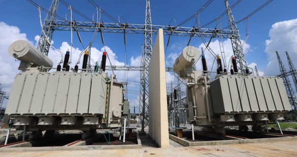
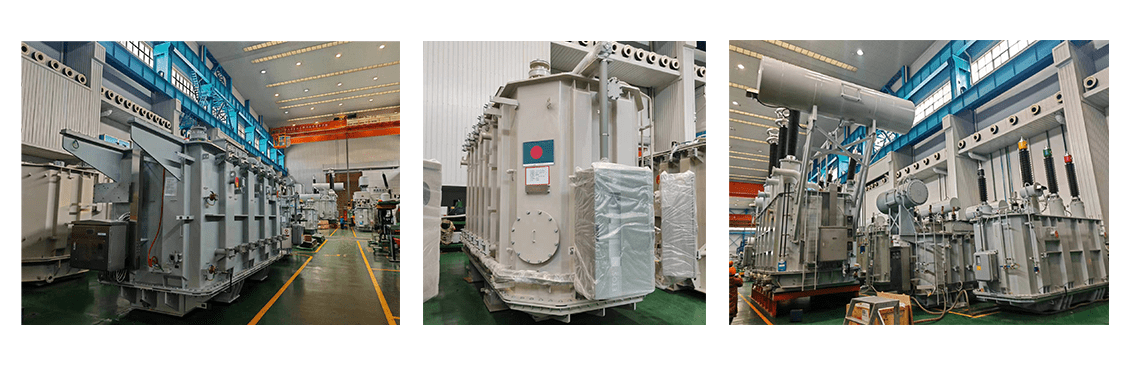
Bangladesh Power Grid Project
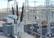
Greece Power grid project
Factory Photos
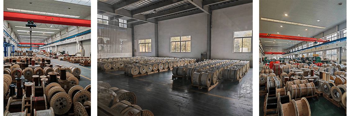
Material stacking area
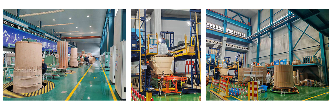
Assembly area
IInspection area
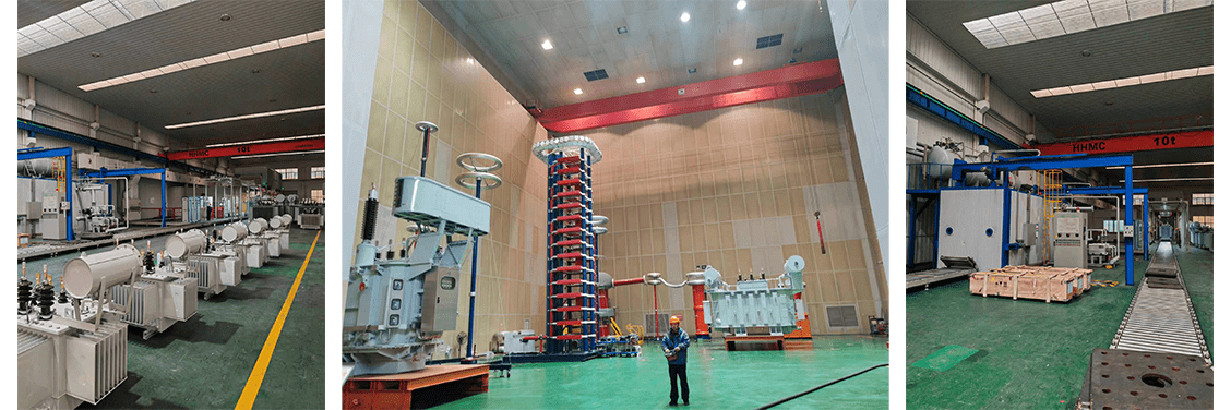
FFinished product
