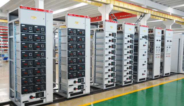
Complete sets of equipment for rated voltages not exceeding 1000V AC and 1500V DC, fixed or mobile, with or without enclosures
One or more low-voltage switchgear and related control, measurement, signalling, protection, regulation and other equipment, by the manufacturer is responsible for the completion of all the internal electrical and mechanical connections, with structural components completely assembled together in an assembly.
Role of low voltage switchgear.
~ power distribution conversion, motor control, reactive power compensation and other purposes.
~Protection of persons against electric shock (direct and indirect contact); ~Protection of equipment against external environmental influences.
~Protection of equipment against external environmental influences.
– Splash
– Squeeze
– Vibration
– Electromagnetic radiation
~Protects against animal entry (snakes, rats, birds ……).

Partially type-tested low-voltage cabinet (PTTA)
A low-voltage complete set of switchgear and control equipment comprising both type-tested and non-type-tested equipment which is derived (e.g. by calculation) from type-tested equipment conforming to the relevant tests.
Fully type-tested low voltage cabinets (TTA)
Low-voltage complete switchgear and controlgear conforming to a recognised type or series, which does not contain differences which may affect performance compared with stereotyped complete equipment which has been verified as conforming to the standard (IEC 61439.1).
For power distribution: feeder cabinet (PCC – Power Control Centre)
For control: Motor Control Center (MCC)
For compensation: Reactive power compensation cabinet (capacitor cabinet)
Fixed type:
The main circuits can only be connected and disconnected when the switchgear is powered off.
Removable type:
The main circuit can be safely disconnected or switched on from the main circuit when the main circuit is energised, with connecting and removable positions.
Withdrawable:
The main circuit can be safely disconnected or switched on from the main circuit with the main circuit energised, with connection, test, separation and removal positions.
Cabinet: The basic structure of the cabinet is assembled.
The basic structure of the cabinet is assembled structure, with C profile (basic modulus E=25mm) as the main structural parts, and fastened with locking self-tapping screws and 8.8 grade high-strength bolts, which results in the cabinet having high precision, good steel, and good grounding continuity.
Separation.
Definition: In order to protect personal and equipment safety, the switchgear cabinet is divided into several independent compartments.
Classification of compartments:
Busbar compartment: including horizontal busbar compartment and vertical busbar compartment
Functional unit room (switch compartment)
Cable outlet room: including cable room
Secondary equipment rooms
For all installations, compliant with standard recommended partitions, options and features: direct or indirect access to live parts is restricted. Covers require the use of tools to remove. Doors providing access to live parts are either key-locked or interlocked with the power supply. Busbar and power connections are insulated/cased, and power terminals need to be insulated.
Separation type.
In case of maintenance on some functional units, partitioning also protects the operator from access to live parts of other functional units.
Type 1: No internal isolation.
Type 2: Busbar isolated from functional units, form 2b: Functional units and terminals separated from busbar, terminals not separated from each other.
Type 3: Busbar isolated from functional units Functional units isolated from each other Outgoing terminals isolated from functional units, form 3b: Functional units separated from each other and from busbar. The terminals are separated from the busbar but not from each other.

Form 4: Busbar and functional units isolated from each other Functional units isolated from each other Outlet terminals isolated from functional units Outlet terminals isolated from each other.
Form 4a: Function units separated from each other and from the busbar. The terminals in the same compartment as the relevant function unit are separated from each other.
Form 4b: The function units are separated from each other and from the busbar. The terminals are separated from each other and from the function units.


