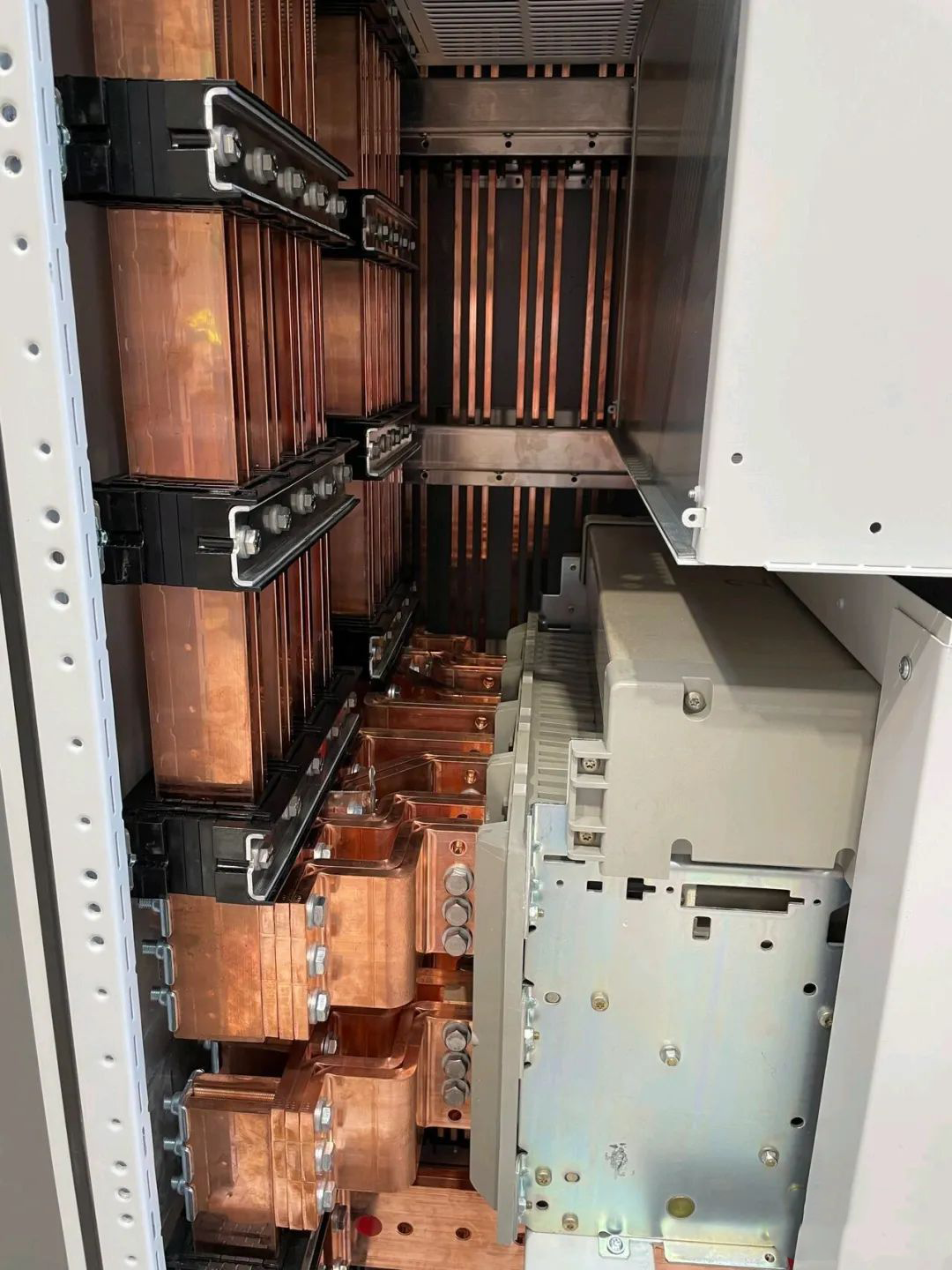
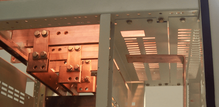
The busbar load capacity is a complex issue, which is a systematic project that needs to be considered within the switchgear system, designed to include cabinet dimensions, cabinet ventilation, and other factors.
There are several formulas for calculating current-carrying capacity, all of which are based on the balance between heat generation and heat dissipation.
The formula for calculating the amount of current carrying capacity in the air of a single copper row:

Where I is the rated current.
R is the resistance value of the copper row, the width of the copper row b, height is a.
A is the heat dissipation surface area of the copper row (m2).
ΔT is the temperature rise, that is, the difference between the surface temperature of the copper row and the ambient temperature; ρ
Kt is the comprehensive heat dissipation coefficient of the surface of the copper row (W/m2-K), which indicates the heat dissipation capacity of the surface of the copper row, and the surface condition of the copper row and the environment, the comprehensive surface heat dissipation coefficient Kt is usually taken as 6~9W/m2-K.
The formula for calculating the load capacity after finishing is as follows:

Take an 80x10mm copper row installed vertically as an example, Kt is 9W/m2-K.

Calculated = 1397.8A
Calculation formula also

I current-carrying capacity, unit A
(Θ-Θn) ambient temperature ≤ 40, unit OC
S busbar cross-sectional area cm2
P busbar circumference cm
ρ resistance of the conductor at 20 degrees Celsius, 1.83 μΩcm for copper
α Resistance temperature coefficient 0,04
K Condition factor for calculating the current-carrying capacity of a single copper row 1
The same calculation with a single 80×10 copper busbar gives a current-carrying capacity of 1713A.
The combined condition factor K consists of the product of k1 to k6.
The coefficient k1 is the coefficient of the number of busbars per phase, when multiple conductors are used in parallel. The total current capacity is less than the rating of a single copper row multiplied by the number of rows used, due to the fact that the copper rows impede the convection and radiation losses of the internal conductors between them.
1 busbar (k1 = 1)
2 or 3 busbars, see table below:

The two key points of this coefficient are e/a, equal cross-sectional area, and the number of roots, which can be seen to be interrelated.
The coefficient k2 is the coefficient for the surface condition of the busbar:
Bare: k2=1
Painted: k2 = 1.15 Painting is good for heat dissipation and increases the amount of current carrying capacity, BTW, and heat-shrink sleeving is also good for heat dissipation.
The coefficient k3 is for the location of the busbar:
Edge mounted busbar: k3=1
1 busbar mounted on a base: k3 = 0.95
Several base-mounted busbars: k3 = 0.75
The coefficient k4 is the coefficient for the location of the busbar installation:
Calm indoor air: k4 = 1
Calm outdoor air: k4 = 1.2
Busbar in non-ventilated duct: k4 = 0.80
The coefficient k5 is for artificial ventilation:
Without artificial ventilation: k5 = 1
Ventilation should be handled on a case-by-case basis and then verified by testing.
The coefficient k6 is the coefficient for the type of current:
For AC currents with frequency ≤ 60 Hz, k6 is determined by the number of roots n per phase and their spacing.
The value of k6 for spacing equal to the thickness of the busbar: n=1,k6=1; n=2,k6=1; n=3,k=0.98
The current carrying capacity of six 10×80 copper rows can be calculated:
I=1397.8xK1…. .K6=1397.8X4.4X0.98=6027.3A
The above calculation is using DC resistivity. For domestic general switchgear, the above current should be on the high side, basically can not pass the temperature rise test, that is due to the domestic switchgear copper rows are arranged more closely, resulting in a significant increase in AC resistance, generally up to 1.2 to 1.5 times the DC resistance, resulting in serious heating.
AC resistance is in the case of alternating current skin effect neighboring effects produced by the impact of the first skin effect, and the shape of the copper row is closely related. The resistance of the conductor is always higher in AC than in DC. The alternating magnetic flux generated by the AC current interacts with the conductor and produces a counterpotential which tends to reduce the current in the conductor. The center portion of the conductor is subjected to the maximum number of magnetic lines of force, the number of line connections decreasing as the edges are approached. The electromotive force produced by self-induction in this way varies in magnitude and phase, as it is greater in the center of the conductor’s cross-section and smaller outside. Consequently, the current tends to flow into the part of the conductor with the smallest opposing electromotive force; that is to say, into the outer surface or edges of the rectangular conductor, producing the so-called “red” effect. The resulting uneven current density increases the resistance of the conductor and leads to increased losses. The magnitude and significance of the effect increases with frequency, conductor size, shape and thickness, but is independent of the magnitude of the flowing current. It should be noted that the skinning effect decreases as the temperature of the conductor increases, thus producing lower than expected AC resistance at high temperatures. This effect is more pronounced for copper conductors than for aluminum conductors of equal cross-section due to their lower resistivity. This difference is particularly noticeable in large busbar cross-sections.
The proximity effect, on the other hand, is affected by the interaction of flowing currents, resulting in a current bias in the direction away from opposing surfaces, resulting in an unbalanced current density and a decrease in overall current density.

Therefore, the current-carrying capacity is not a simple application, and the busbar arrangement, cabinet structure and so on are closely related. The temperature rise of the switchgear is not just a busbar problem, but also the heat generation of the components, high localized heat generation, eddy currents and so on, all of which lead to temperature rise exceeding the standard, and it is necessary to solve the problem of temperature rise exceeding the standard of the switchgear through the system design.


