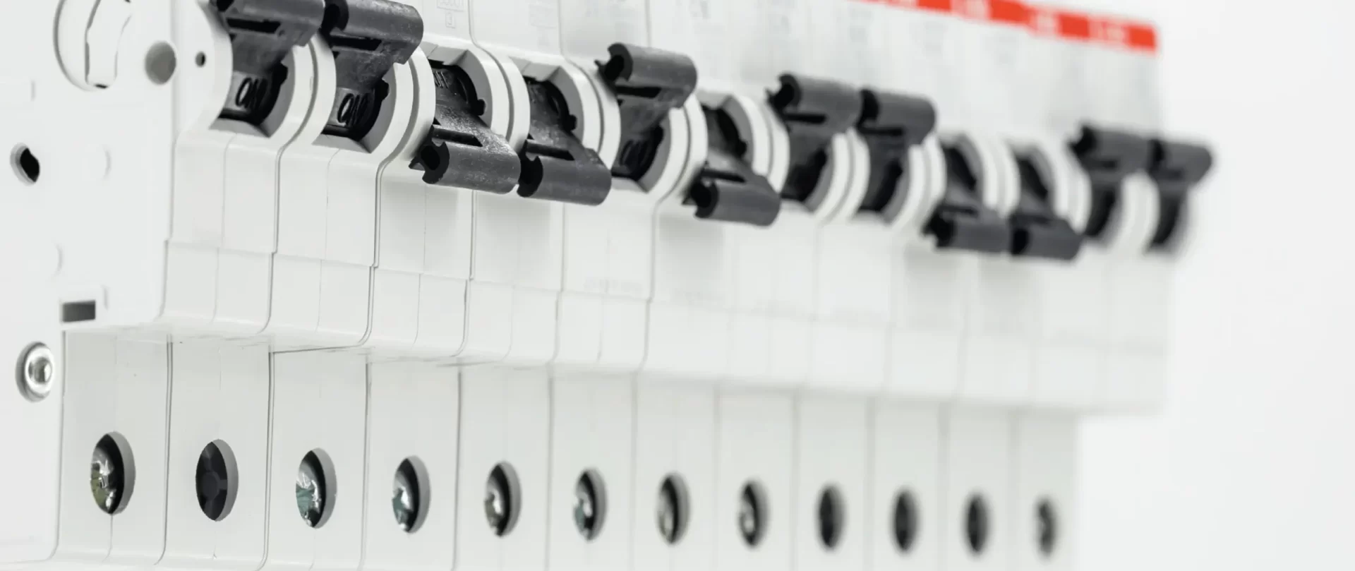
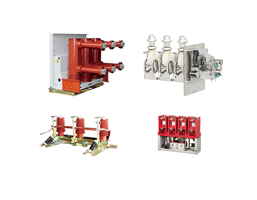
The current switches commonly used in switchgear are generally categorized as:
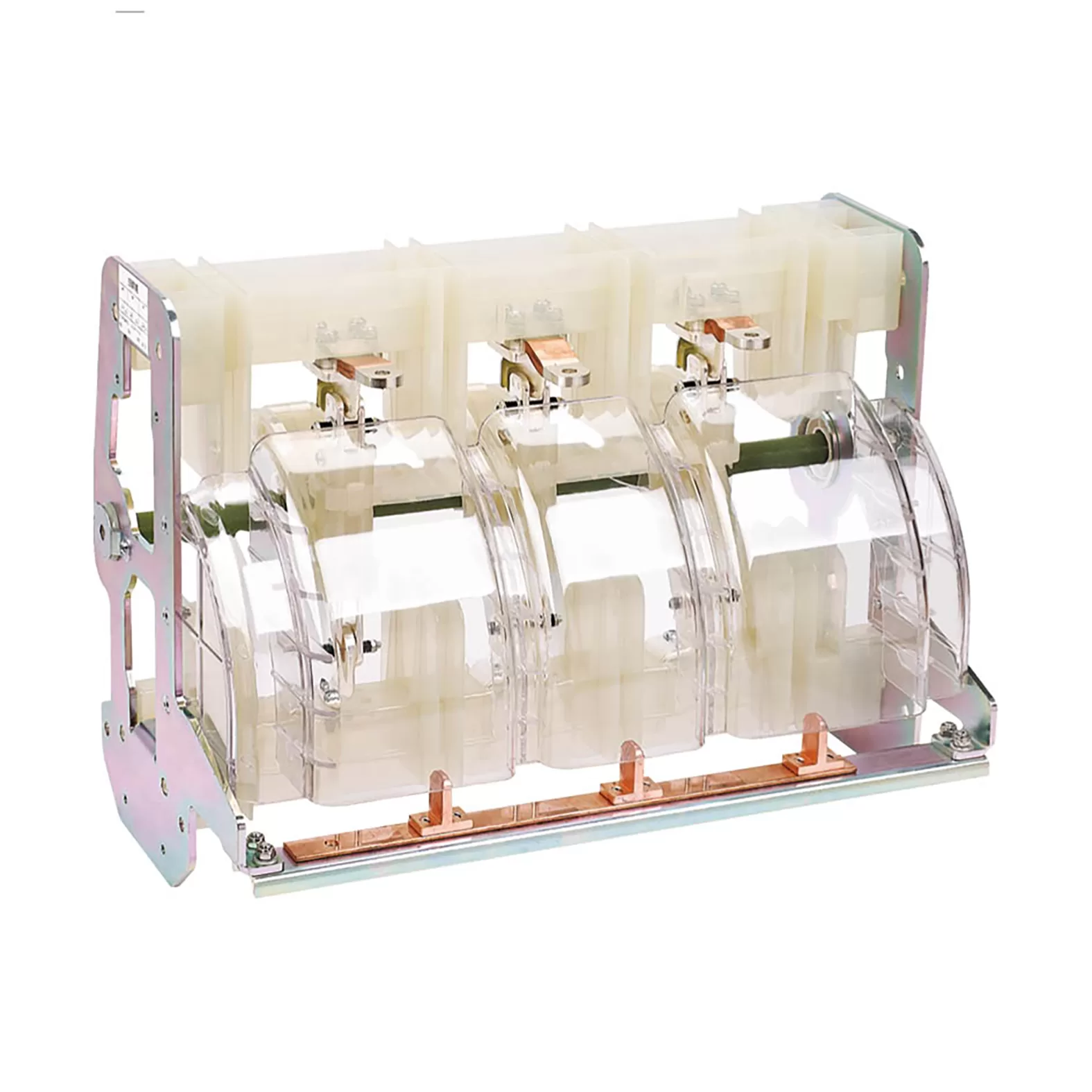
Isolation that is to separate the two parts to achieve the safety requirements, electrical isolation to achieve the two parts of the circuit to achieve a safe electrical gap, even if there are different voltages on both sides, but also do not interfere with each other, their own safe operation, dual power feed to the isolation cabinet to achieve the two sections of the bus respective operation.
Isolation switches also require visible breaks, appliances suitable for isolation in the disconnected position must have an isolation distance that meets the requirements of the isolation function, and should provide one or more methods of displaying the position of the main contacts:.
With the position of the actuator;
A separate mechanical indicator;
Visualization of all active contacts.
The validity and mechanical strength of each method of indication provided by the appliance shall be verified in accordance with the provisions When the manufacturer specifies or provides a means of locking the appliance in the open position, locking in the open position shall only be possible when the main contacts are in the open position, this method of construction being verified in accordance with the provisions.
The mechanical connection in the open position ensures that the desired isolation distance is maintained under certain conditions.
To ensure safe isolation of the circuit, it is usually associated with an earthing switch.
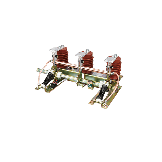
For safety when working on a circuit, it grounds the disconnected active conductor.
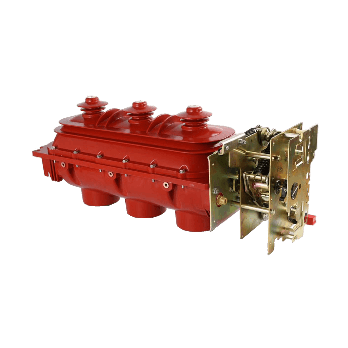
Mechanical connecting device capable of establishing, maintaining and disconnecting current under normal circuit conditions, including overload current during operation.
Used to control circuits (open and close) and usually used to perform insulation functions.
It is often used in conjunction with fuses in public and private medium voltage distribution networks.
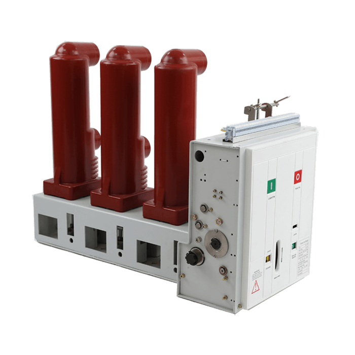
A mechanically connected device with a single stationary position, not manually controlled, capable of establishing, maintaining and disconnecting current under normal circuit conditions, including operating voltage conditions.
Suitable for very frequent functional operation, mainly for motor control.
Used in conjunction with fuses for short circuit protection.
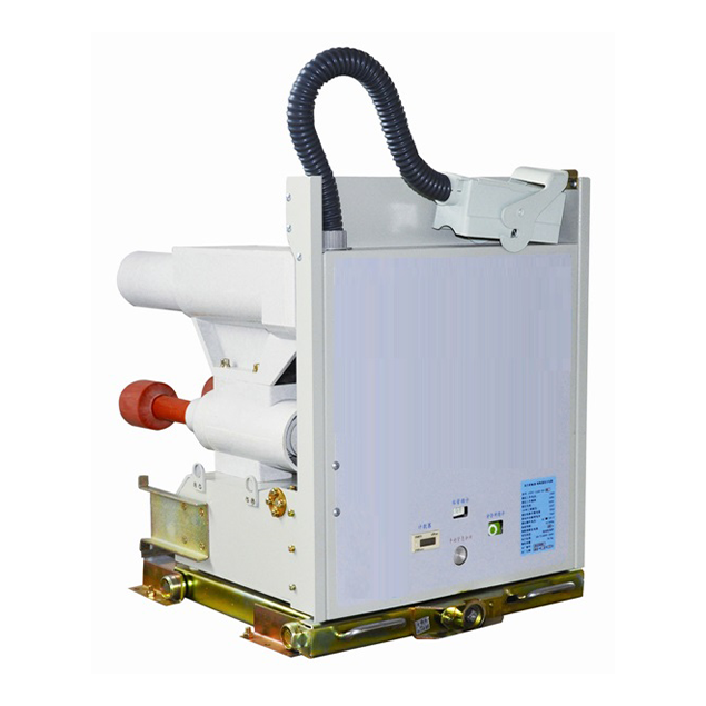
Mechanical connection devices capable of establishing, maintaining and disconnecting current under normal circuit conditions and under certain abnormal circuit conditions (e.g. short circuits).
General purpose connecting device. In addition to controlling the circuit, it secures the circuit against electrical faults. Replacement contactor for control of large medium voltage motors
Switching Performance
| Switch Type | Opening | Closing | Isolated or not | ||||
| No-load | Load | Short circuit | No-load | Load | Short circuit | ||
| Disconnect Switch | YES | NO | NO | YES | NO | YES | YES |
| Grounding Switch | YES | NO | NO | YES | NO | YES | NO |
| Load Switch | YES | YES | NO | YES | YES | YES | YES |
| Contactor | YES | YES | NO | YES | YES | YES | NO |
| Circuit Breaker | YES | YES | YES | YES | YES | YES | NO |
The ideal circuit breaker is a device that can instantaneously break the current.
However, no mechanical device is capable of disconnecting current without the help of electricity. This phenomenon limits the overvoltage and releases the electromagnetic energy of the circuit, but it delays the complete disconnection of the current.
The ideal switch
Theoretically, the ability to instantaneously disconnect a current means that it is possible to make a direct transition from the state of a conductor to that of an insulator. The “ideal” resistance, therefore, the switch must immediately go from zero to infinity.
The device must be able to:
Absorb the electromagnetic energy accumulated in the circuit before breaking.
Withstand the overvoltage (Ldi/dt) that appears at both ends of the device break, which has an infinite value if it passes from insulator to conductor in a very short time. This will inevitably lead to dielectric breakdown. Assuming that these problems have been eliminated and perfect synchronization has been achieved between the natural transfer of current to 0 and the insulating conductor transition of the device, there is still another difficult aspect to consider, namely the transient recovery voltage (TRV). Indeed, just after the current interruption, the recovery voltage at the switch terminals is added to the network voltage, when the recovery voltage of the reactive circuit is at its maximum value. This is not suddenly interrupted due to the parasitic capacitance of the network. When the voltage is restored to coincide with the network voltage, an unstable state is established. This voltage is called the transient recovery voltage (TRV), and depending on the network characteristics, the rate of increase (dv/dt) of this voltage can be quite large (a few kV/microseconds). In simple terms, this means that in order to avoid disconnection faults, the ideal switch must be able to withstand a voltage of several kV in less than a microsecond after the transition from conductor-insulator.
Disconnecting with an Arc
Arcing exists for two reasons:
Due to the uncertainty of the measurement sequence, it is practically impossible to precisely separate the contacts at the natural 0 current point: for an rms value of 10 kA, the instantaneous current 1 ms before 0 is still 3000 A. If the device is insulated immediately, the instantaneous overvoltage Ldi/dt appearing at the ends of the device terminals would be infinite and lead to an immediate breakdown of the still small internal contact gap.
Contact separation must be carried out at a sufficiently high rate so that the dielectric strength between the contacts is greater than the transient recovery voltage. This requires near-infinite mechanical energy, which in practice no device can provide.
The arc break process is divided into three phases:
The sustained arc phase, the
The arc extinguishing phase, and
Post-arc phase
Arc propagation stage
Before reaching zero current, the two contacts separate, resulting in dielectric breakdown of the internal contact medium. The arc that occurs consists of a plasma column of ions and electrons, which come from the contact medium or from the metal vapor released by the electrodes. This arc column remains electrically conductive as long as its temperature is maintained at a fairly high level. Thus, the arc is “sustained” by the energy dissipated by the Joule effect.
Due to the arc resistance and the surface voltage drop (cathode and anode voltages), the voltage that appears between the two contacts is called the arc voltage (Ua). Its value depends on the nature of the arc and is influenced by the current strength and the heat exchange with the medium (wall, material, etc.). This heat exchange is radiative, convective and conductive and characterizes the cooling capacity of the device.
The role of the arc voltage is crucial, since the power consumed by the device during disconnection depends to a large extent on the arc voltage.
Arc extinguishing phase
With the medium rapidly becoming insulated again, the current opening corresponding to arc extinguishing is accomplished under zero current conditions. To do this, the channels of ionized molecules must be broken. The extinction process is accomplished in the following manner: close to zero current, the arc resistance increases according to a curve which depends mainly on the de-ionization time constant in the contact medium, the value of this resistance is not infinite and the current passes through the device again after the arc discharge due to the transient recovery voltage appearing at the terminals.
If the power dissipated by the Joule effect exceeds the characteristic cooling capacity of the device, the dielectric is no longer cooled: thermal conduction then occurs and another dielectric breakdown occurs: leading to thermal failure.
On the other hand, if the increase in voltage does not exceed a certain critical value, the resistance of the arc can increase rapidly so that the power dissipated into the dielectric is less than the cooling capacity of the device, thus avoiding thermal runaway.
Post-arc phase
For successful disconnection, it is also necessary that the dielectric recovery rate be much faster than the TRV, otherwise dielectric breakdown will occur. At the instant a dielectric breakdown occurs, the dielectric becomes conductive again, resulting in a transient phenomenon. These post-disconnection dielectric failures are called:
Re-ignition if it occurs within a quarter cycle after zero current, and Re-breakdown if it occurs thereafter.
TRV in the standard
Although the rate of increase of TRV has a fundamental effect on the disconnect capacity of a device, it is not possible to precisely determine this value for all network configurations.
The standard IEC 62271-100 defines a range of TRV for each rated voltage corresponding to the requirements usually encountered.
The breaking capacity of a circuit breaker is defined as the maximum current that can be broken at its rated voltage and corresponding rated TRV.
| Rated Voltage Ur (kV) | 7.2 | 12 | 17.5 | 24 | 36 | 52 |
| TRV (kV) | 12.3 | 20.6 | 30 | 41 | 62 | 89 |
| t3 (μs) | 52 | 60 | 72 | 88 | 108 | 132 |
| Rate of rise (Uc / t3) | 0.24 | 0.34 | 0.42 | 0.47 | 0.57 | 0.68 |

